


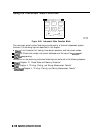
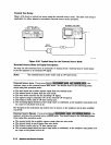

The
System
Menu
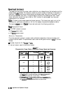
The @ZGT] key provides access to the system menu. This menu leads to additional menus
which control various aspects of the analyzer system. The following softkeys are located
within the system menu:
w
i&&;&&a
allows
you
to
produce
me
stamps
on
plots
and
printouts.
n
~c~~~~~
::,J$&@
provides
access
to
tests&,
raw
offs&,
ad
spur avoidance
fun&ions.
..:::.:.::.:
:.::..,
L
.,.,
.
.
.
,;>.,
.z.
n
J;;X#ZV:m
provides access to the limits menu.
b
.,.........
I..:><Yi:..;<<.:
::::
i......
i.;;:
.‘.“”
~;~~<~~“:~~~~
.,mpj<,
y
.:::.
.>.>>
9
~~~~#~
.;:m!:
(Option 010 Only) provides access to the transform menu.
:::..:.:.~...~~~
.,,.,,;
..,....A.
:i
L..<
.:.
<
.:.:
.
.._
.,...x:.;..
,,,,,,,
s
.,.,.
:.:.,s
..:
i
.
‘~~~~~~~~~
(Option
&-y-J
my)
proedes
access
to
the
hmofic
mode
menu.
1,,..1~
::...::...:...<<
.:._...:
.,,,....
z.x:i.
,,,.:........
c.:.
_
_i_
/
.;;;;;;;;;,
.~~
~
./
_..__
.
”
,,,
.“.”
,,
ii?
,,,.
.“’
..,
.;:;,,
,;:;.
.;$
~~~~~:..~~~~::~
provides access to the instrument mode menu.
.:
z
__...
h>:>.<<<.,..;,:
,,,.....
i....~~~~~
. . . . . . . il;;:.:. :.i::...i;;....:
..,....
:.s.<.:.
.
~~~~~~
provides
acceSS
to
*e
service
menu
(see
the
Hp
87533Ndwork
Ana21/zer
P
..:
.:...:....~.>::~<
.,..
.A...
m;;
. . . . . . . . .
. . . . . .
..A.
:.:!
. . . . .
. . . . . . .
. . . . .
.
/
f!ikmi%
tiih).
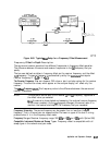
The Limits Menu
This menu can be accessed by pressing
~~~~~~~~~
softkey within the system menu.
..:..
i.~...,...=........;.....
.
.
.
. .
..A
.:::::.: ;;;
.
...:.
..::
.,..
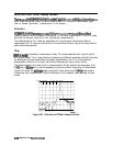
You can have limit lines drawn on the display to represent upper and lower limits or device
specillcations
with which to compare the test device. Limits are defined in segments, where
each segment is a portion of the stimulus span. Each limit segment has an upper and a lower
starting limit value. Three types of segments are available: flat line, sloping line, and single
point.
Limits can be
defined
independently for the two channels, up to 22 segments for each channel.
These can be in any combination of the three limit types.
Limit testing compares the measured data with the defined limits, and provides pass or fail
information for each measured data point. An out-of-limit test condition is indicated in five
ways: with a FAIL message on the screen, with a beep, by changing the color of the falling
portions of a trace, with an asterisk in tabular listings of data, and with a bit in the HP-IB
event status register B. (The analyzer also has a BNC rear panel output that includes this status,
but is only valid for a single channel measurement.)
Note
The limit test output has three selectable modes. For more information, refer to
Chapter 2, “Making Measurements.
n
Limit lines and
limit
testing can be used simultaneously or independently. If limit lines are
on and limit testing is off, the limit lines are shown on the display for visual comparison and
adjustment of the measurement trace. However, no pass/fail information is provided. If limit
testing is on and limit lines are off, the specified limits are still valid and the pass/fail status is
indicated even though the limit lines are not shown on the display.
Limits
are entered in tabular form. Limit lines and
limit
testing can be either on or off while
limits are defined. As new limits are entered, the tabular columns on the display are updated,
and the
limit
lines (if on) are modified to the new definitions. The complete limit set can be
offset in either stimulus or amplitude value.
6-114
ApplicationandOperationConcepts