


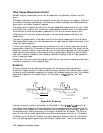
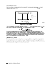
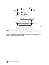
Device Measurement
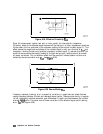
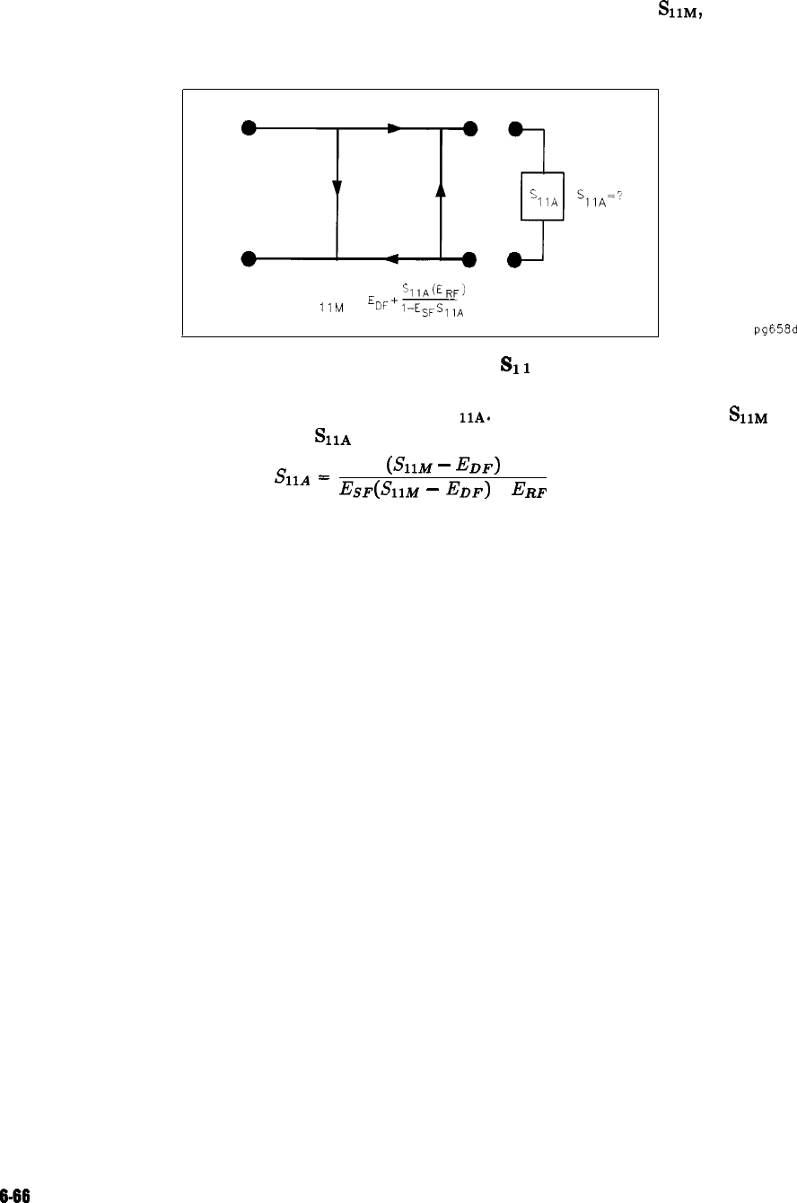
Now the unknown is measured to obtain a value for the measured response,
frequency (see Figure 6-41).
Figure 6-41. Measured
SI
1
E&J,
at each
s
i1M
=
E
'~IA(~RF)
DF+
mA
pg658d
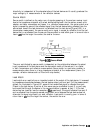
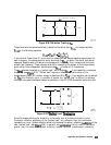
This is the one-port error model equation solved for
S
11A.
Since the three errors and
SLIM
are
now known for each test frequency,
&IA
can be computed as follows:
&lA
=
(SllM
-
J%F)
J%F(S~IM
-
EDF)
+
ERF
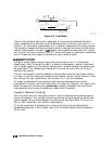
For reflection measurements on two-port devices, the same technique can be applied, but
the test device output port must be terminated in the system characteristic impedance. This
termination should have as low a reflection coefficient as the load used to determine directivity.
The additional reflection error caused by an improper termination at the test device’s output
port is not incorporated into the one-port error model.
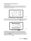
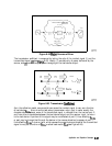
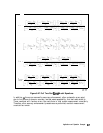
Two-Port
Error Model
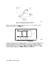
The error model for measurement of the transmission coefficients (magnitude and phase) of a
two-port device is derived in a similar manner. The potential sources of error are frequency
response (tracking), source match, load match, and isolation (see Figure 6-42). These errors are
effectively removed using the full two-port error model.
6-66 Application and Operation Concepts