


3.
lb
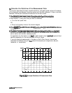
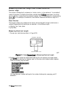
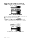
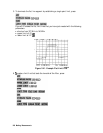
activate a marker to measure the group delay at a particular frequency, press:
(%ZQ
and turn the front panel knob, or enter a value from the front panel keypad.
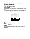
Figure 2-37. Group Delay Example Measurement
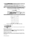
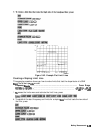
Group delay measurements may require a specific aperture
(AF’)
or frequency spacing between
measurement points The phase shift between two adjacent frequency points must be less than
180°,
otherwise incorrect group delay information may result.
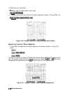
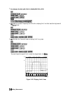
4.
‘lb
vary the effective group delay aperture from
minimum aperture (no smoothing) to
appro~ately
1%
of
the
frequency
span,
press:
LAvg)
~~~~~~~~~~~~
:::::.
.:::..:::..:..;
.
.
..A..
s.;..i
. . . . . . . . . . .
. . . .
2......22;;;:
. . . . . . . . . . .. . .
..A
.:.:::*
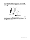
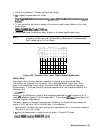
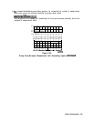
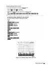
When you increase the aperture, the analyzer removes fine grain variations from the
response. It is critical that you specify the group delay aperture when you compare group
delay measurements.
Figure 2-38. Group Delay Example Measurement with
Smoothing
aw000008
244 Making Measurements