Figures
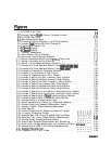
l-l. HP 8753E Front Panel
...........................
l-2.
Analyzer Display
(Single
Channel, Cartesian Format)
.............
l-3. HP 8753E Rear Panel
...........................
2-l.
Basic Measurement Setup
.........................
2-2. Example of Viewing Channels 1 and 2 Simultaneously
............
2-3. Example
Dual
Channel With Split Display On
................
2-4. Example of a Display Title
.........................
2-5.
3-Channel
Display
.............................
2-6.
4-Channel
Display
.............................
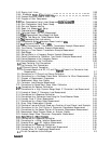
2-7. Duplexer Measurement
...........................
2-8. Active Marker Control Example
.......................
2-9. Active and Inactive Markers Example
....................
2-10. Marker Information Moved into the Softkey Menu Area
...........
2-11. Marker Information
on
the Graticules
....................
2-12. Marker 1 as the Reference Marker Example
...........
. .
........
t
........
2-13. Example of a Fixed Reference Marker Using
~~~~:~~;~~.~
.......
...........
....
.......... ..............
2-14. Example of a Fixed Reference Marker Using
~~~~,,
...........
..................................................
2-15. Example of Coupled and Uncoupled Markers
................
2-16. Example of a Log Marker in Polar Format
..................
2-17. Example of Impedance Smith Chart Markers
................
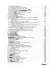
2-18. Example of Setting the Start Frequency Using a Marker
...........
2-19. Example of Setting the Stop Frequency Using a Marker
...........
2-20. Example of Setting the Center Frequency Using a Marker
..........
2-21. Example of Setting the Frequency Span Using Marker
............
2-22. Example of Setting the Reference Value Using a Marker
...........
2-23. Example of Setting the Electrical Delay Using a Marker
...........
2-24. Example of Searching for the Maximum Amplitude Using a Marker
......
2-25. Example of Searching for the Minimum Amplitude Using a Marker
......
2-26. Example of Searching for a
Target
Amplitude Using a Marker
.........
2-27. Example of Searching for a Bandwidth Using Markers
............
2-28. Example Statistics of Measurement Data
..................
2-29. Device Connections for Measuring a Magnitude Response
...........
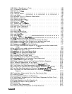
2-30. Example Magnitude Response Measurement Results
.............
2-31. Example Insertion Phase Response Measurement
..............
2-32. Phase Samples
...............................
2-33. Device Connections for Measuring Electrical Length . . . . .
2-34. Linearly Changing Phase . . . . . . . . . . . . . . . . . .
2-35. Example Best Flat Line with Added Electrical Delay . . . . .
2-36. Deviation From Linear Phase Example Measurement . . . . .
2-37. Group Delay Example Measurement . . . . . . . . . . . .
2-38. Group Delay Example Measurement with Smoothing . . . . .
2-39. Group Delay Example Measurement with Smoothing Aperture
I:
2-40. Connections for SAW Filter Example Measurement . . . . . .
2-41.ExampleFlatLimitLine
. . . . . . . . . . . . . . . . . .
2-42. Example Flat Limit Lines . . . . . . . . . . . . . . . . . .
........
........
........
........
........
........
ncreased
. . .
........
........
........
l-4
l-7
l-11
2-3
2-6
2-6
2-9
2-11
2-12
2-16
2-18
2-18
2-19
2-20
2-21
2-22
2-23
2-24
2-25
2-26
2-27
2-27
2-28
2-29
2-30
2-31
2-32
2-33
2-34
2-35
2-36
2-37
2-38
2-38
2-39
2-40
2-41
2-42
2-43
2-44
2-44
2-45
2-46
2-48
2-49
Contents-17


