


Conversion Loss Using the Frequency Offset Mode
Conversion loss is the measure of efficiency of a mixer. It is the ratio of side-band IF power to
RF signal power, and is usually expressed in
dB.
(‘lb
express ratios in
dR,
the
dBm
power in the
denominator must be subtracted from the
dBm
power in the numerator.) The mixer translates
the incoming signal, (RF), to a replica, (IF), displaced in frequency by the local oscillator,
(Lo>.
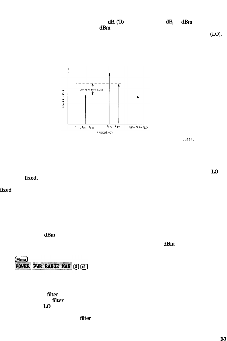
Frequency translation is characterized by a loss in signal amplitude and the generation of
additional sidebands. For a given translation, two equal output signals are expected, a lower
sideband and an upper sideband.
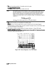
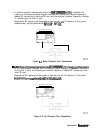
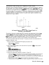
FREQUENCY
pg694d
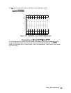
Figure 3-4.
An Example Spectrum of RF, LO, and IF Signals Present in a
Conversion Loss Measurement
The analyzer allows you to make a swept RF/IF conversion loss measurement holding the
Lo
frequency
fixed.
You can make this measurement by using the analyzer’s frequency offset
measurement mode. This mode of operation allows you to offset the analyzer’s source by a
Rxed
value, above or below the analyzer’s receiver. That is, this allows you to use a device
input frequency range that is different from the receiver input frequency range.
The following procedure describes the swept IF frequency conversion loss measurement of a
broadband component mixer:
1. Set the LO source to the desired CW frequency and power level.
CW frequency = 1000 MHz
Rower = 13
dBm
2. Set the desired source power to the value which will provide -10
dRm
or less to the R
channel input. Press:
3. Calibrate and zero the power meter.
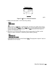
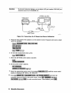
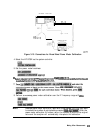
4. Connect the measurement equipment as shown in Figure 3-5.
q
The low pass
filter
is required to limit the range of frequencies passed into the R channel
input port. The
flter
is selected to pass the IF frequencies for the measurement but
prevent the
L0
feedthrough and unwanted mixer products from confusing the phase lock
loop operation.
q
A pad is used to isolate the
titer
and improve the IF port match for the mixer.
q
The attenuation of the power splitter is used to improve the RF port match for the mixer.
Making Mixer Measurements
3-7