


Filtering
Harmonics, linearity, and spurious signals also introduce errors that are not removed by
frequency response calibration. These errors are smaller with a narrowband detection scheme,
but they may still interfere with your measurements. You should
filter
the IF signal to reduce
these errors as much as possible.
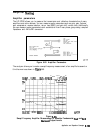
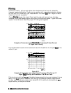
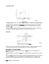
Correct
filtering
between the mixer’s IF port and the receiver’s input port can eliminate
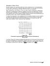
unwanted mixing and leakage signals from entering the analyzer’s receiver. Figure 6-90 shows
a plot of mixer conversion loss when proper IF filtering was neglected.
I
j
j
j
j
i
i
!
j
j
II
I
Ii
I
I I I I
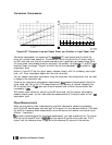
Example of Conversion Loss versus Output Frequency Without Correct
IF Signal Path Filtering
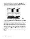
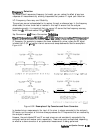
Figure 6-91 shows the same mixer’s conversion loss with the addition of a low pass
filter
at the
mixer’s IF port.
pge1a
1-c
Figure 6-91.
Example of Conversion Loss versus Output Frequency With Correct IF
Signal
P&&I
Filtering and Attenuation at all Mixer Ports
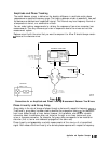
Filtering is required in both fixed and broadband measurements, but you can implement it more
easily in the fixed situation. Therefore, when conllguring broad-band (swept) measurements,
you may need to trade some measurement bandwidth for the ability to more selectively
Alter
signals entering the analyzer’s receiver.
6.160
ApplicationandOperationConcepts