


..:::c. ..:.:.:.:
“)
,,
.:.:.:.:..
_
,.
,.,..:
_
_
.,.
.:
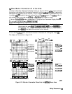
Press
Lcal]
.~~~~~~;~~~~.~.
&@f&
&+%Rf~
::.:.
Note
Make sure you connect the calibration standards to the Rx port of the test
adapter (or a cable attached to it) for the FORWARD calibration, and the
Antenna port for the REVERSE calibration.
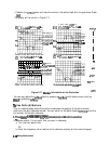
12. When the calibration has been completed, save this state in the analyzer:
13. Connect the DUT to the test adapter.
14. Enable both auxiliary channels 3 and 4:
..z.
/
:+
..;p
. . . . . . . . .
:..:,;:
“,:,::...:...:.:.:.:..,,,::
,;..:.:;:;..
:
:::
. .
. .
..::::
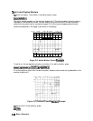
Press (Display)
~~~~~~~
,;f@%JR~
set
AI&
~:~I$&&
to ON, press
@GiJ
and set
&J@$HA#
to
..;;..~.....~._;
.
. ..a
ii..;;;;;
ii
x.... . . . . .
.A....
. .
..A
. . . . .
. .
..i
>n;;.~
~7::
..:.
.:’
,,,,....
. . . . . . . . . . . . . . . . . . . . L.
ON.
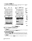
15. Set up a two-graticule, four-channel display:
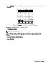
16. Set the measurement parameters (channel 1 should be active):
a.
fiess
IMeas]
~~~~
.:..
..,.,.:,..,,
.
. . .
.
.,.:::::
This is the transmission of the
‘k-to-Ant
path.
,*;.................,.
,,.
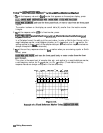
b. Press
@iGil
to activate channel 3, press
@$g;.
This is the reflection at the
TX
port.
C.
Press
c-1
f&&g;
This is the transmission of the Ant-to-Rx path.
i
/
...*.
i.
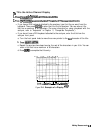
d.
F%ess
@G-T)
to activate channel 4, press
$%$.‘.
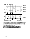
This is the reflection at the Rx port.
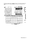
The display will be similar to Figure 2-7.
Making Measurements
2-15