


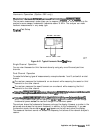
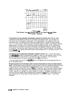

from the reference plane (where the calibration standards are connected) to the discontinuity
and back: 18.2 nanoseconds. The distance shown (5.45 meters) is based on the assumption
that the signal travels at the speed of light. The signal travels slower than the speed of light
in most media (e.g. coax cables). This slower velocity (relative to light) can be compensated
for by adjusting the analyzer relative velocity factor. This procedure is described later in this
section under “Time domain bandpass.”
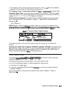
Time Domain Bandpass
This mode is called
bandpass
because it works with band-limited devices. Traditional TDR
requires that the test device be able to operate down to
dc
Using
bandpass
mode, there are no
restrictions on the measurement frequency range.
Bandpass
mode characterizes the test device
impulse response.
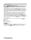
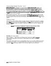
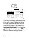
Adjusting the Relative Velocity Factor
A marker provides both the time (x2) and the electrical length (x2) to a discontinuity.
To
determine the physical length, rather than the electrical length, change the velocity factor to
that of the medium under test:
2. Enter a velocity factor between 0 and 1.0 (1.0 corresponds to the speed of light in a
vacuum). Most cables have a velocity factor of 0.66 (polyethylene dielectrics) or 0.70 (teflon
dielectrics).
Note
‘RI
cause the markers to read the actual one-way distance to a discontinuity,
rather than the two-way distance, enter one-half the actual velocity factor.
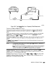
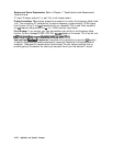
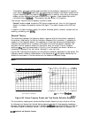
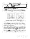
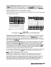
Reflection Measurements Using
Bandpass
Mode
The
bandpass
mode can transform reflection measurements to the time domain. Figure 6-62
(a) shows a typical frequency response reflection measurement of two sections of cable.
Figure 6-62
(b)
shows the same two sections of cable in the time domain using the
bandpass
mode.
Application and Operation Concepts
6-127