


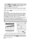
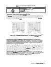

Time domain low pass
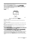
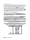
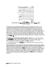
This mode is used to simulate a traditional time domain reflectometry (TDR) measurement. It
provides information to determine the type of discontinuity (resistive, capacitive, or inductive)
that is present. Low pass provides the best resolution for a given bandwidth in the frequency
domain. It may be used to give either the step or impulse response of the test device.
The low pass mode is less general-purpose than the
bandpass
mode because it places strict
limitations on the measurement frequency range. The low pass mode requires that the
frequency domain data points are harmonically related from dc to the stop frequency. That is,
stop = n x start, where n = number of points For example, with a start frequency of 30
kHz
and 101 points, the stop frequency would be 3.03 MHz. Since the analyzer frequency range
starts at 30
kHz,
the dc frequency response is extrapolated from the lower frequency data. The
requirement to pass dc is the same limitation that exists for traditional TDR.
Setting frequency range for time domain low pass
Before a low pass measurement is made, the measurement frequency range must meet the
(stop
=
n
x
&,&)
reqdement
described
above.
me
~~~~~~~~~~~~~~
softkey
perfoms
. .
..i..
.<:.:.
.:..:.:
/.~.:,.>;;.::
. . . . . . . . . .
;;.:I
. .
..T
:.
:
..,....
. . .
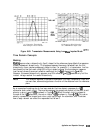
this function automatically: the stop frequency is set close to the entered stop frequency, and
the start frequency is set equal to stop/n.
If the low end of the measurement frequency range is critical, it is best to calculate
approximate
v&es
for
the
St&
ad
stop
frequencies
before
pressing
,~~~~~~~~~~~,
and calibrating. This avoids distortion of the measurement results.
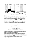
‘Ib
see an example,
select the preset values of 201 points and a 300
kHz
to 3
GHz
frequency range. Now press
~~~~~~~~~~~~
ad
observe
me
change
h
frequency
values.
me
stop
frequency
changes
_/.~~~~
. .
. . . . . . .
.
. . .. . . . . . . . .
..>.z.
. .
..A
. . . .
.
..z...............
.._......
. . . . . . . . . . . . . . . . . . ..~.~~.. . . . .
..A.
ii
;;>........;
. .
..A
i.
,.,....
i:
::..>;::..
to 2.999
GHz,
and the start frequency changes to 14.925 MHz. This would cause a distortion of
measurement results for frequencies from 300
kHz
to 14.925 MHz.
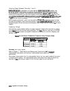
Note
If the start and stop frequencies do not conform to the low pass requirement
before a low pass mode (step or impulse) is selected and transform is turned
on, the analyzer resets the start and stop frequencies. If error correction is on
when the frequency range is changed, this turns it off.
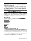
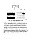
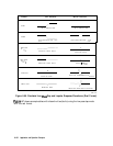
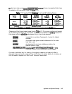
‘Ibble
6-11. Minimum Frequency Ranges for Time Domain Low Pass
Number of
Points
Minimnm
F-4-w
m
3
30kHztQ0.OfIMHz
11
3OkHzto0.33MHz
26
30kHzto0.78MHz
51
3OkHzto1.53MHz
101
30kHzto3.03 MHz
201
30
kHzti
6.03 MHz
401
3OkHzto12.03MHz
801
30
kHzto24.03
MHz
1601
3OkHzto43.03MHz
6-130 Application and Operation Concepts