


Time Domain Operation (Option 010)
With Option 010, the analyzer can transform frequency domain data to the time domain or
time domain data to the frequency domain.
In normal operation, the analyzer measures the characteristics of a test device as a function
of frequency. Using a mathematical technique (the inverse Fourier transform), the analyzer
transforms frequency domain information into the time domain, with time as the horizontal
display axis. Response values (measured on the vertical axis) now appear separated in time
or distance, providing valuable insight into the behavior of the test device beyond simple
frequency characteristics.
Note
An HP 8753E can be ordered with Option 010, or the option can be added at a
later date using the HP
85019B
time domain retrofit kit.
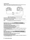
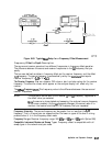
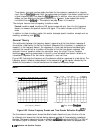
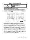
The transform used by the analyzer resembles time domain reflectometry (TDR) measurements
TDR measurements, however, are made by launching an impulse or step into the test device
and observing the response in time with a receiver similar to an oscilloscope. In contrast, the
analyzer makes swept frequency response measurements, and mathematically transforms the
data into a TDR-like display.
The Transform Menu
(:.:.:.:.:.:.:~.:.....:.:.:.:.~
:
:.y
““.:..:.:.:.~~:.:.:.:.:.:.:...,.~:.:.~~:.:.:.~:.~:.,::.~:.:~:.:.::.~:
.,.,.;
_
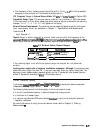
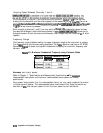
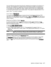
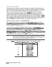
The analyzer’s transform menu can be accessed by pressing
&G’Z]
~~~~~~~~~~.
This
..-....~............................
/i
;;;;;;;.
menu consists of the following softkeys:
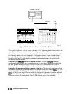
The analyzer has three frequency-to-time transform modes:
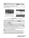
Time domain bandpass mode simulates the time domain response of an impulse input and is
designed to measure band-limited devices. Although this mode is the easiest to use, it results
inless
time domain resolution than low pass mode, and may result in some magnitude errors
at low frequencies when gating is used. For devices that are not band-limited, one of the low
pass modes is recommended.
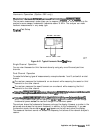
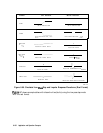
Time domain low pass
step mode
simulates the time domain response of a step input. As in
a traditional TDR measurement, the distance to the discontinuity in the test device, and the
type of discontinuity (resistive, capacitive, inductive) can be determined.
Application and Operation Concepts
6-125