


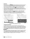
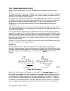
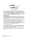

lncldent
I
Match
TransmItted
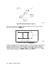
Figure 6-31. Load Match
The error contributed by load match is dependent on the relationship between the actual
output impedance of the test device and the effective match of the return port (port 2). It is
a factor in all transmission measurements and in reflection measurements of two-port devices.
The interaction between load match and source match is less significant when the test device
insertion loss is greater than about 6
dD.
However, source match and load match still interact
with the input and output matches of the DUT, which contributes to transmission measurement
errors. (These errors are largest for devices with highly reflective ports)
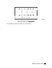
Isolation
(crosstalk)
Leakage of energy between analyzer signal paths contributes to error in a transmission
measurement, much like directivity does in a reflection measurement. Isolation is the vector
sum of signals appearing at the analyzer samplers due to crosstalk between the reference and
test signal paths. This includes signal leakage within the test set and in both the RF and IF
sections of the receiver.
The error contributed by isolation depends on the characteristics of the test device. Isolation
is a factor in high-loss transmission measurements However, analyzer system isolation is more
than sufficient for most measurements, and correction for it may be unnecessary.
For measuring devices with high dynamic range, accuracy enhancement can provide
improvements in isolation that are limited only by the noise floor. Generally, the isolation falls
below the noise floor, therefore, when
performing
an isolation calibration you should use a
noise reduction function such as averaging or reduce the IF bandwidth.
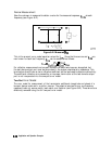
Frequency Response (Tracking)
This is the vector sum of all test setup variations in which magnitude and phase change as a
function of frequency. This includes variations contributed by signal-separation devices, test
cables, adapters, and variations between the reference and test signal paths This error is a
factor in both transmission and reflection measurements.
For further explanation of systematic error terms and the way they are combined and
represented graphically in error models, refer to the “Characterizing Microwave Systematic
Errors” next.
6-60 Application and Operation Concepts