


13.
Press (Ghan] again.
Observe that the LED is flashing, indicating that channel 3 is active.
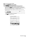
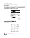
14. Rotate the front panel control knob and notice that marker 2 still moves on all four
channel traces.
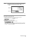
15. To independently control the channel markers:
**,,
.:.
.::.
Press (Marker)
‘~~~~~~::::.~~,
set
~jQ#$JR&~~-
to UNCOUPLED.
. .
. .../ i
. . . . .
i......;.;;;;
.
.......... . .
i.i
....
. . .
. . .
..i..
i/......ii
Rotate the front panel control knob. Marker 2 moves only on the channel 3 trace.
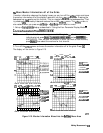
Once made active, a channel can be
conhgured
independently of the other channels in most
variables except stimulus. For example,
once~channel3
is active, you can change its format to a
;
. . . . . .
.a:
;:.,
,.:.:...:..
Smith chart by pressing
@GZ)
$#$Z~B&KX..
;;;
.._...,..........................
T
.
....
. . . . . . . . . .
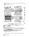
Quick Four-Parameter Display
.;. ,..,
.,.
.,. .
.
.
.
.
.
.
.
.
.
.
The
~~~.~~~~~~~~~:,;
menu
gives
you
a
choice
of
standard
channel
conmations
and
>:;:,I;
1.:.
$,>,;>
,,.:.::.,;,.,..:.
:.:
.
.
.
.
:.:.:.:.::..~:.~~~~~~::~~:.:.:.:.~~:::,~:.;,:.:.,.:.:.:.:.:.:.,.:
_;
,,,,,,i:
.,.,
<:...
parameter assignments.
..::
.,.....,.,.......
.,.,
.;:..
,.
. . . . . .
_
:...
. . . . . .
Press
~~~~~
in place of step 6.
For more information about the
~~~~~~~~~~~~~
menu, refer to chapter 6, “Application
and Operation Concepts.
n
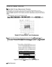
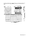
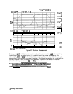
Characterizing a Duplexer
The following example demonstrates how to characterize a
3-port
device, in this case a
duplexer. This measurement utilizes four-parameter display mode.
A duplexer’s three ports are:
n
Transmit
(TX)
n
Receive (Rx)
n
Antenna (Ant)
There are two signal paths through a duplexer: from Tx to Ant, and from Ant to Rx. The
two signal paths are offset in frequency from each other and have the antenna (Ant) port in
common.
This example displays the tr
ansmission
(TX-to-Ant and Ant-to-Rx) characteristics of the
duplexer in the top half of the display, and the reflection characteristics (Tx and Rx ports) in
the bottom half. Therefore, the stimulus is set up so that it is centered midway between the
transmit and receive frequencies of the duplexer, and the span is set to cover the combined
receive and transmit frequencies.
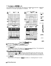
Other display configurations are possible. For example, the display can be configured so that
the transmission and reflection of the
TX-Ant
path is shown in the top half of the display, and
the transmission and reflection of the Ant-Rx path is shown in the bottom half of the display.
Making
Meesurements
2-13