


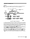

Connection Considerations
Adapters
lb
minimize the error introduced when you add an adapter to a measurement system, the
adapter needs to have low SWR or mismatch, low loss, and high repeatability.
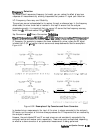
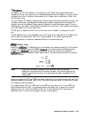
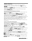
Worst
Case
System
DiBtiVity
28d.B
17dEI
14
dE3
Leakage signals
Reflected signal
44
3
;;
i
c,
* Coupler has
4OdE3
Directivity
\.
_
_
_
_
_
+
.
:
-----_____-
s-..
Adapter
__ ----:*
x
.,.....-.,
. . . . . . . .
“,.I
1
D</
pGi-j
%kd
=PAd+Pd
7mm
---EmMale
.
\
7mmtoSMA(f)
swR:1.05
7mmtoN(f)+N(m)toSMA(f)
swRz1.05
SWIM.25
7mmtoN(m)+N(f)toSMA(m)+SMAQto(f)
swR:1.05
swRz1.25
swR:1;15
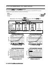
Figure 6-99. Adapter Considerations
pg6237
In a reflection measurement, the directivity of a system is a measure of the error introduced
by an imperfect signal separation device. It typically includes any signal that is detected at the
coupled port which has not been reflected by the test device. This directivity error will add
with the true reflected signal from the device, causing an error in the measured data. Overall
directivity is the limit to which a device’s return loss or reflection can be measured. Therefore,
it is important to have good directivity to measure low reflection devices.
For example, a coupler has a 7 mm connector and 40
dB
directivity, which is equivalent to a
reflection
coeflkient
of
p=O.Ol
(dlrectivity
in
dB
= -20 log
p).
Suppose we want to connect to
a device with an SMA male connector. We need to adapt from
7
mm to SMA.
If we choose a precision 7 mm to SMA adapter with a SWR of 1.06, which has
p=
0.03, the
overall directivity becomes
p-O.04
or 28
dE%
However, if we use two adapters to do the same
job, the reflection from each adapter adds up to degrade the directivity to 17
dB.
The last
example shown in Figure 6-99 uses three adapters that shows an even worse directivity of
14
dB.
It is clear that a low SWR is desirable to avoid degrading the directivity of the system.
Application and Operation Concepts
6-169