


Note
Because power meter calibration requires a longer sweep time, you may want
to
reduce
the
number
of
points
before
pressing
:~~;-c~~~~~~.
After
the
power meter calibration is
Gnashed,
return the number of points
to
its
original
value and the analyzer will automatically interpolate this calibration. Some
accuracy will be lost for the interpolated points.
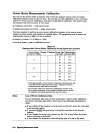
The analyzer will use the data table for subsequent sweeps to correct the output power
level at each measurement point. Also, the status annunciator PC will appear on the
analyzer display.
Note
. . . . . . . . . . . . . . . . . .
.:.:
:.;:
:.:..
I
You can abort the calibration sweep by pressing
~~~;;~:~~~~~~~:..
. . . . . . ..ii . . . . . .
i
ii
.:
ii
i...;;;;;.:.::.~
10. Remove the power sensor from the analyzer test port and connect your test device.
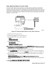
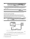
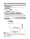
Using Continuous Correction Mode
You can set the analyzer to update the correction table at each sweep (as in a leveling
application), using the continuous sample mode. When the analyzer is in this mode, it
continuously checks power at every point in each sweep. You must keep the power meter
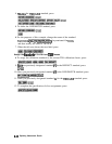
connected as shown in Figure 5-9. This mode is also known as power meter leveling, and the
speed is limited by the power meter.
Note
You may level at the input of a device under test, using a
2-resistor
power
splitter or a directional coupler before the device; or level at the output of
the device using a 3-resistor power splitter or a bidirectional coupler after the
device.
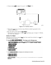
NETWORK ANALYZER
KGE
TEST
POWER SENSOR
/
1
CONNECT FOR INITIAL SWEEP
2 CONNECT FOR SUBSEQUENT SWEEPS
pg616e
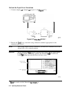
Figure
5-9. Continuous Correction Mode for Power Meter Calibration
1. Connect a power splitter or directional coupler to the port supplying RF power to your test
device, as shown in Figure 5-9.
2. Set test port power to approximate desired leveled power
538
Optimizing Measurement Results