


FORWARD
I
I
I
I
E
/F
I
1
I
s
I
1
I
21A
ETF
s
I
21M
RF IN l
-
1
1
b
EDF\r
I
5
I
E
E
I
IIA
I
LF
SF
I
‘22A
I
I
l
U
T
A
I
s
I
IlM
ERF
I
s
12A
I
I
I
PORT 1
PORT 2
REVERSE
I
I
I
s
21A
I
ERR
‘22M
1
I
l
I
I
ESR
I
‘12M
ELF!
I
dEDP
.
I
1
1
l RF IN
E
TR
I
’
12A
I 1
I
I
I
.
E
XR
I
I
pg663d
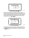
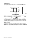
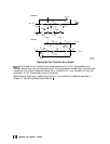
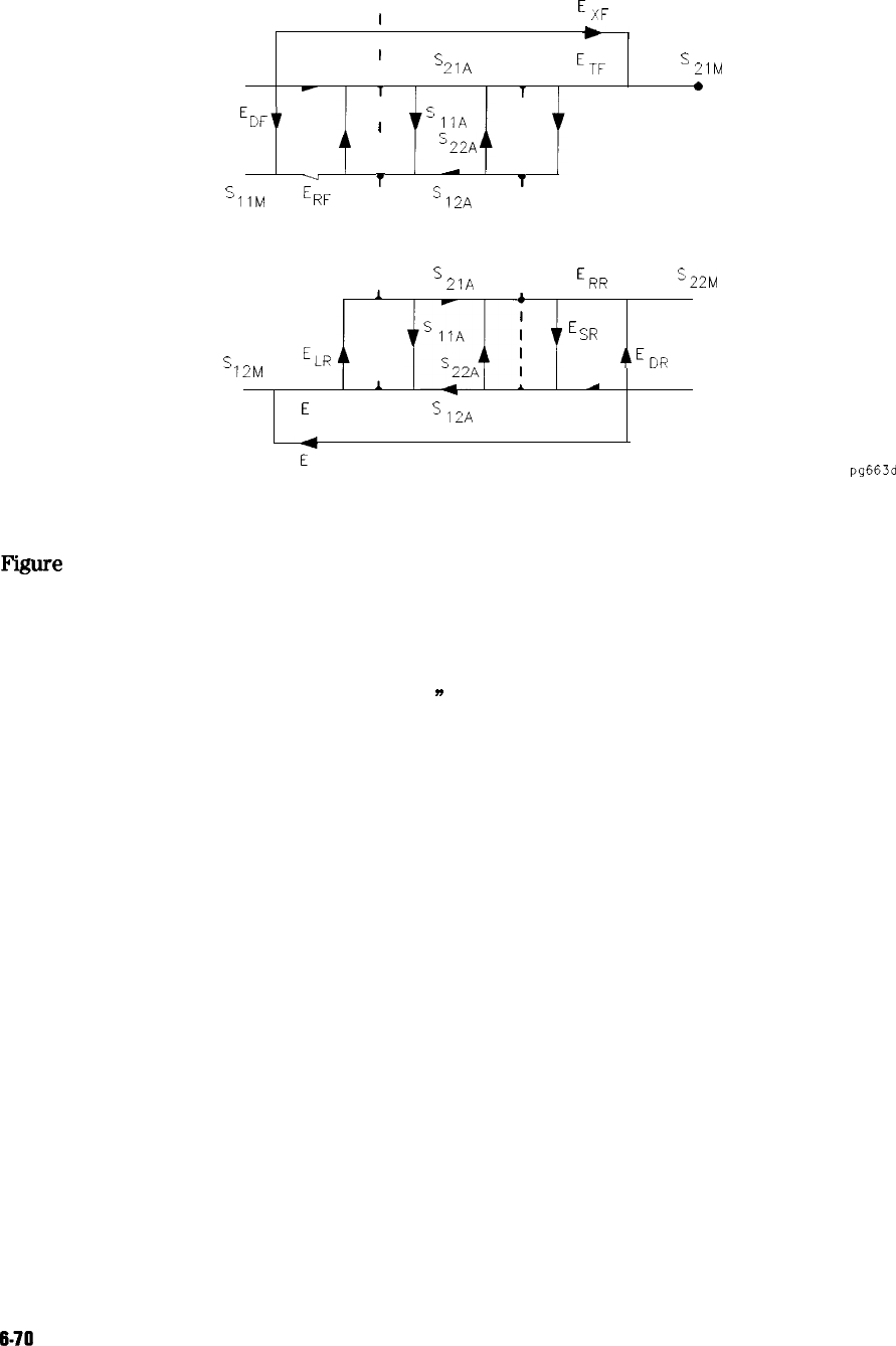
Figure 6-46. Full Two-Port Error Model
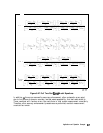
F’igure
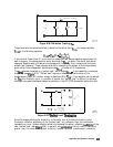
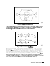
6-47 shows the full two-port error model equations for all four S-parameters of a
two-port device. Note that the mathematics for this comprehensive model use all forward and
reverse error terms and measured values. Thus, to perform full error-correction for any one
parameter, all four S-parameters must be measured.
Applications of these error models are provided in the calibration procedures described in
Chapter 5, “Optimizing Measurement Results.
n
6-70
Application and Operation Concepts