


lksting A Device with Limit Lines
Limit testing is a measurement technique that compares measurement data to constraints that
you define. Depending on the results of this comparison, the analyzer will indicate if your
device either passes or fails the test.
Limit testing is implemented by creating individual flat, sloping, and single point limit lines on
the analyzer display. When combined, these lines can represent the performance parameters
for your device under test. The limit lines created on each measurement channel are
independent of each other.
This example measurement shows you how to test a
bandpass
filter using the following
procedures:
n
creating flat limit lines
n
creating sloping limit lines
n
creating single point limit lines
n
editing limit segments
n
running
a limit test
Setting Up the Measurement Parameters
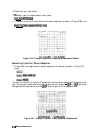
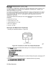
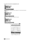
1. Connect your test device as shown in Figure 2-40.
NETWORK ANALYZER
DEVICE UNDER TEST
pg67e
Figure 2-40. Connections for SAW Filter Example Measurement
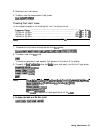
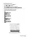
2. Press
IpresetJ
and choose the measurement settings. For this example the measurement
settings are as follows:
You may
also
want to select settings for the number of data points, power, averaging, and IF
bandwidth.
3. Substitute a thru for the device and perform a response calibration by pressing:
246 Making Measurements