


Response and Isolation Error-Correction for Transmission Measurements
This procedure is intended for measurements that have a measurement range of greater than
90
dB.
1. Press
IpresetJ.
2. Select the type of measurement you want to make.
q If you want to make a transmission measurement in the forward direction
(&I),
press:
q If you want to make a transmission measurement in the reverse direction
(E&2),
press:
3. Set any other measurement parameters that you want for the device measurement: power,
number of points, IF bandwidth.
4.
‘lb
access the measurement correction menus, press:
.
5.
If your calibration kit is different than the kit specified under the
~~~~;~~~~~l,,::,,,,::~
softkey,
press:
If your type of calibration kit is not listed in the displayed menu, refer to the “Modifying
Calibration Kit Standards” procedure, located later in this chapter.
6. To select a response and isolation correction, press:
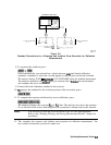
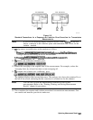
7. Make a
“thru”
connection between the points where you will connect your device under
test.
Note
Include any adapters that you will have in the device measurement. That is,
connect the standard device to the particular connector where you will connect
your device under test.
8.
To
measure the standard, when the displayed trace has settled, press:
The
analyzer displays
WAIT
-
MEASURING CAL STANDARD
during the standard measurement.
.::.:....,x
.,.,.,.,
.,
./
The analyzer underlines the
!@##!&I?.
softkey after it measures the calibration standard, and
computes the error coefficients
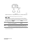
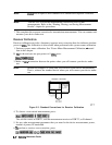
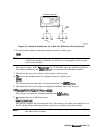
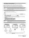
9. Connect impedance-matched loads to PORT 1 and PORT 2, as shown in Figure 5-5. Include
the adapters that you would include for your device measurement.
5-16 Optimizing Measurement Results