


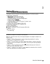

Measurement Considerations
To
ensure successful mixer measurements, the following measurement challenges must be taken
into consideration:
w
Mixer Considerations
. . . .
q
Muummmg
Source and Load Mismatches
q
Reducing the Effect of Spurious Responses
q
Eliminating Unwanted Mixing and Leakage Signals
n
Analyzer Operation
q
How RF and IF Are Defined
q
Frequency Offset Mode Operation
q
Differences Between Internal and External R channel Inputs
q
Rower Meter Calibration
Minimizing Source and Load Mismatches
When characterizing linear devices, you can use vector accuracy enhancement to
mathematically remove all systematic errors, including source and load mismatches, from your
measurement. This is not possible when the device you are characterizing is a mixer operating
over multiple frequency ranges. Therefore, source and load mismatches are not corrected for
and will add to overall measurement uncertainty.
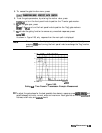
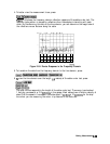
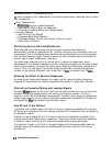
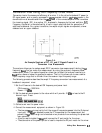
You should place attenuators at all of the test ports to reduce the measurement errors
associated with the interaction between mixer port matches and system port matches ‘lb avoid
overdriving the receiver, you should give extra care to selecting the attenuator located at the
mixer’s IF port. For best results, you should choose the attenuator value so that the power
incident on the analyzer R channel input is less than -10
dBm
and greater than -35
dBm.
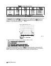
Reducing the Effect of Spurious Responses
By choosing test frequencies (frequency list mode), you can reduce the effect of spurious
responses on measurements by avoiding frequencies that produce IF signal path distortion.
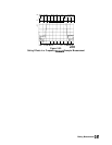
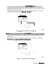
Eliminating Unwanted Mixing and Leakage Signals
By placing
Wers
between the mixer’s IF port and the receiver’s input port, you can eliminate
unwanted mixing and leakage signals from entering the analyzer’s receiver. Filtering is
required in both tied and broadband measurements Therefore, when configuring broad-band
(swept) measurements, you may need to trade some measurement bandwidth for the ability to
more selectively
filter
signals entering the analyzer receiver.
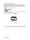
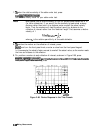
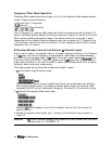
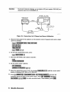
How RF and IF Are Defined
In standard mixer measurements, the input of the mixer is always connected to the analyzer’s
RF source, and the output of the mixer always produces the IF frequencies that are received by
the analyzer’s receiver.
However, the ports labeled RF and IF on most mixers are not consistently connected to the
analyzer’s source and receiver ports, respectively. These mixer ports are switched, depending
on whether a down converter or an up converter measurement is being performed.
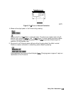
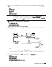
It is important to keep in mind that in the setup diagrams of the frequency offset mode, the
analyzer’s source and receiver ports are labeled according to the mixer port that they are
connected to.
3-2
Making Mixer Measurements