


. . . . . . .
./
..%.......
press
m
~~~~~~~~~~~~‘~~
~~~~~~~~~~~~‘-I~~~,
and
the
analyzer
m
display
the
.: .:. . . . . . . . . .
i:::.::
ii
..A..
i;;:..:.~...;..
ii.
. . . . . . . .
....
...... ........ ......
;;.;
................
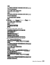
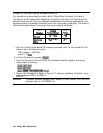
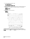
following sequence commands:
SEQUENCESEQ2
Start of Sequence
WAITx
.1x1
MANUALTRG
ONPOINT
TITLE
FREQ:CWUP
PERIPHERAL HPIB ADDR
19x1
TITLETO PERIPHERAL
PERIPHERAL HPIB ADDR
21x1
TITLETO PERIPHERAL
DECR LOOP COUNTER
IFLOOP
COUNTERoOTHENDO
SEQUENCE2
TITLE
MEASUREMENT COMPLETED
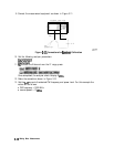
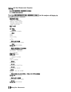
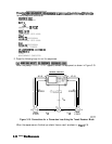
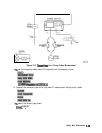
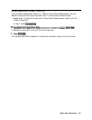
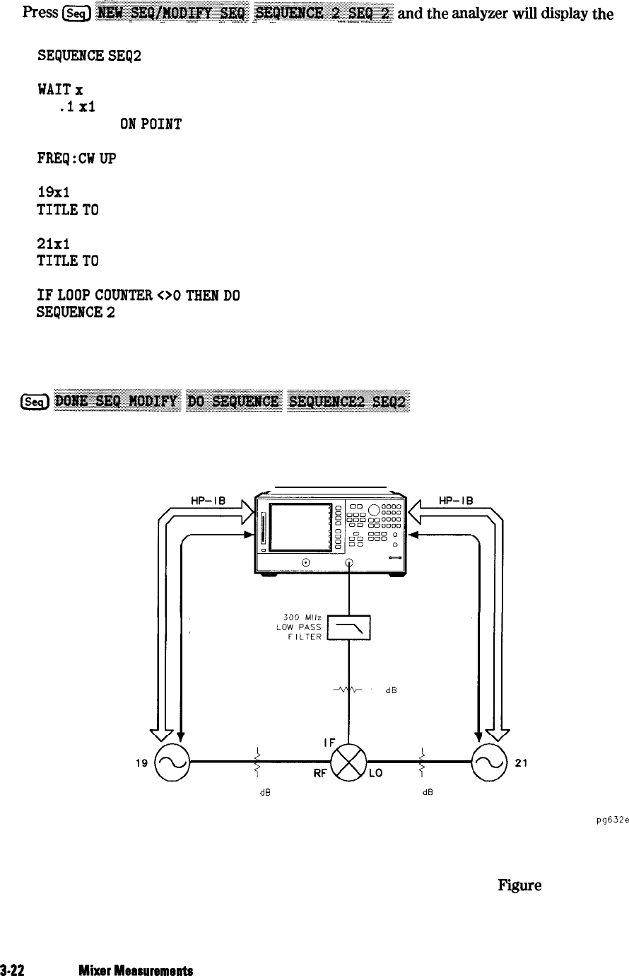
2. Press the following keys to run the sequences:
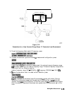
When the prompt
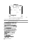
CONNECT MIXER
appears, connect the equipment as shown in Figure 3-15.
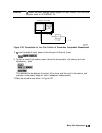
NETWORK ANALYZER
EXT
EXT
REFERENCE
REFERENCE
10
dB
EXTERNAL
RF SOURCE
6
dB
3
dB
EXTERNAL
LO SOURCE
pg632e
Figure 3-15. Connections for a Conversion Loss Using the Tuned Receiver Mode
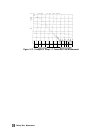
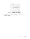
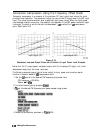
When the sequences are finished you should have a result as shown in
F’igure
3-16.
3-22
Making
Mixer
Mearursments