


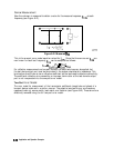
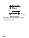


Electrical Offset
Some standards have reference planes that are electrically offset from the mating plane of the
test port. These devices will show a phase shift with respect to frequency.
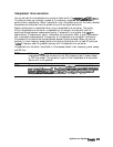
‘lhble
6-4 shows
which reference devices exhibit an electrical offset phase shift. The amount of phase shift can
be calculated with the formula:
4
=
(360
x f x
1)/c
where:
f = frequency
1 = electrical length of the offset
c
=
speed of light (3 x
10s
meters/second)
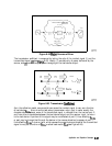
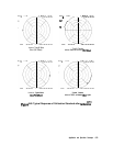
Fringe Capacitance
All open circuit terminations exhibit a phase shift over frequency due to fringe capacitance.
Offset open circuits have increased phase shift because the offset acts as a small length of
transmission line. Refer to lhble 6-4.
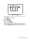
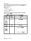
able
6-4. Calibration Standard Types and Expected Phase Shift
lbst
Port
Connector Type
7-mm
Type-N male
3.5mm
male
3.6~mm
female
2.4mm
male
2.4mm
female
Type-N female
760
Type-N female
7-mm
Ty-pe
N-male
3.6-mm
male
Standard
Type
Sh0I.t
o&et
short
open
Offset Open
Expected
Phase
Shift
1800
lS(y
+
(360
x
f
x
0
c
0’
+
Lpacitance
o”
+
$4
capac*tance
+
(=ox.fxO
c
3.6~mm
female
2.4nun
male
2.4mm
female
Type N-female
open
o”
+
&apacrtance
+
(360 x
f
x I)
c
763 Type-N female
6-74
Application and Operation Concepts