


PORT
PORT
‘5
0)
0
c
-
(Ti
s?,~
souRcE~iLEs3
lrsll
‘3
1rELF4\_LoAo
-
MATCH
MATCH
A
ERF
512
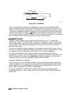
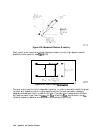
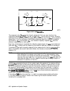
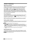
Figure 6-44. Load
Match
Em
pg661d
The measured value,
SLIM,
consists of signal components that vary as a function of
the
relationship between
Esr
and
&A
as well as E
LF
and
f&2&
so the input and output reflection
coefficients of the test device must be measured and stored for use in the
&IA
error-correction
computation. Thus, the test setup is calibrated as described above for reflection to establish
the directivity,
Enr
, source match,
Esr
, and reflection frequency response,
Em,
terms for
reflection measurements on both ports.
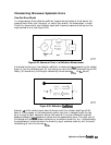
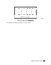
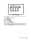
Now that a calibrated port is available for reflection measurements, the
thru
is connected and
load match,
ELF,
is determined by measuring the reflection coefficient of the thru connection.
Transmission signal path frequency response is then measured with the thru
COMected.
The
data is corrected for source and load match effects, then stored as transmission frequency
response, Err.
Note
It is very important that the exact electrical length of the thru be known.
Most calibration kits assume a zero length thru. For some connection types
such as Type-N, this implies one male and one female port. If the test system
requires a non-zero length thru, for example, one with two
male
test ports, the
exact electrical delay of the thru adapter must be used to modify the built-in
calibration kit definition of the thru.
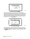
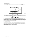
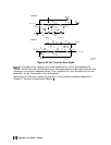
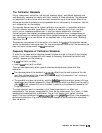
Isolation,
EXF,
represents the part of the incident signal that appears at the receiver without
actuaIly
passing through the test device (see Figure 6-45). Isolation is measured with the test
set in the transmission configuration and with terminations installed at the points where the
test device will be connected. Since isolation can be lower than the noise floor, it is best to
increase averaging by at least a factor of four during the isolation portion of the calibration.
___
;,..
_*
.,.
,:,
:~:.:.,.:.:.:.:.:.:.:.::.:.:.,.:.:.:.:.,.:...:.:.:.:.:.:.:.:~.:.:.:.:.:.:::::::::.:::::::::::::::::::::.,:
f
::;:..:.:.::::.:...:...
.:.;
The
i##y&~‘;,,f
‘C,
,:cp:g
i
:
)
,,
(,,,
,j
s
_,/_
_
~~.,.;,~.,.::~~~~~~.:.~,.~.:.~.~.:.,:
_
::.:.~:.~~~~:.::.:.::::.:.:.:.:.:.~~;:;
_
_;
,.;
/
,.,.,.,.,.,.,.,.,...,.
;;,,
..:.
_
..,.
~.~~.~~.~~~~~~~
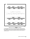
softkey under the
(GJ
menu allows a calibration sequence to
resume after a change to the averaging factor.
If the leakage
fails
below the noise floor, it is best to increase averaging before calibration.
In this case, ommitting isolation is better than measuring the isolation standards without
increasing the averaging factor.
6-66
Application and Operation Concepts