


I
I
I
I
I
I
I I I
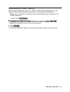
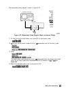
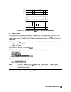
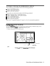
Figure 3-27. Example Mixer ID to RF Isolation Measurement
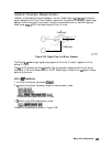
RF Feedthrough
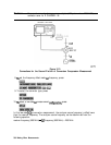
The procedure and equipment configuration necessary for this measurement are very similar
to those above, with the addition of an external source to drive the mixer’s
LC
port as we
measure the mixer’s RF feedthrough. RF feedthrough measurements do not use the frequency
offset mode.
1. Select the CW
Lo
frequency and source power from the front panel of the external source.
CW frequency = 300 MHz
Power = 10
dBm
2. Initialize the analyzer by pressing
B.
3. To select the analyzer’s frequency range and source power, press:
This signal stimulates the mixer’s RF port.
4. To select a ratio measurement, press:
Note
Isolation is dependent on
Lo
power level and frequency. To ensure good
test results, you should choose these parameters as close to actual operating
conditions as possible.
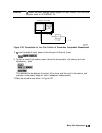
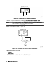
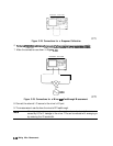
5.
Make the connections as shown in Figure 3-28.
Making
Mixer Measurements
3-36