


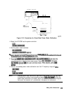
Fixed IF Mixer Measurements
A fixed IF can be produced by using both a swept RF and LO that are offset by a certain
frequency. With proper filtering, only this offset frequency will be present at the IF port of the
mixer.
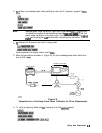
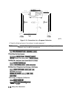
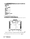
This measurement requires two external RF sources as stimuli. Figure 3-15 shows the hardware
configuration
for the fixed IF conversion loss measurement. This example measurement
procedure uses the analyzer’s test sequence function for automatically controlling the two
external synthesizers (with SCPI commands), and making a conversion loss measurement in
tuned receiver mode. The test sequence function is an instrument automation feature internal
to the analyzer. For more information on the test sequence function refer to “Test Sequencing”
located in Chapter 2.
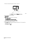
Tuned Receiver Mode
The analyzer’s tuned receiver mode allows you to tune its receiver to an arbitrary frequency
and measure signal power. This is only possible if the signal you wish to analyze is at an exact
known frequency. Therefore, the RF and
Lo
sources must be synthesized and synchronized
with the analyzer’s time base.
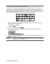
Sequence 1 Setup
The following sequence initializes and calibrates the network analyzer. It then initializes the
two external sources prior to measurement. This sequence includes:
n
putting the network analyzer into tuned receiver mode
n
setting up a frequency list sweep of 26 points
n
performing a response calibration
n
prompting the user to connect a mixer to the test set up
n
inimg
a loop counter value to 26
n
addressing
and
configuring
the two sources
n
calling the next measurement sequence
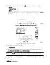
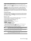
1. Make the following connections as shown in Figure 3-14. Set the HP-IB address of the
external RF source to 19 and the external Ix) source to 21.
2.
Confirm that the external sources are configured to receive commands in the SCPI
programming language and that their output power is switched on.
Note
You may have to consult the User’s Guide of the external source being used to
determine how to set the source to receive SCPI commands.
3. Be sure to connect the 10 MHz reference signals of the external sources to the EXT REF
connector on the rear panel of the analyzer (a BNC tee must be used).
Note
If the 10 MHz reference signals of the external sources are connected together,
then it will only be necessary to connect one reference signal from one of the
sources to the EXT REF connector of the analyzer.
Making Mixer Measurements 3-17