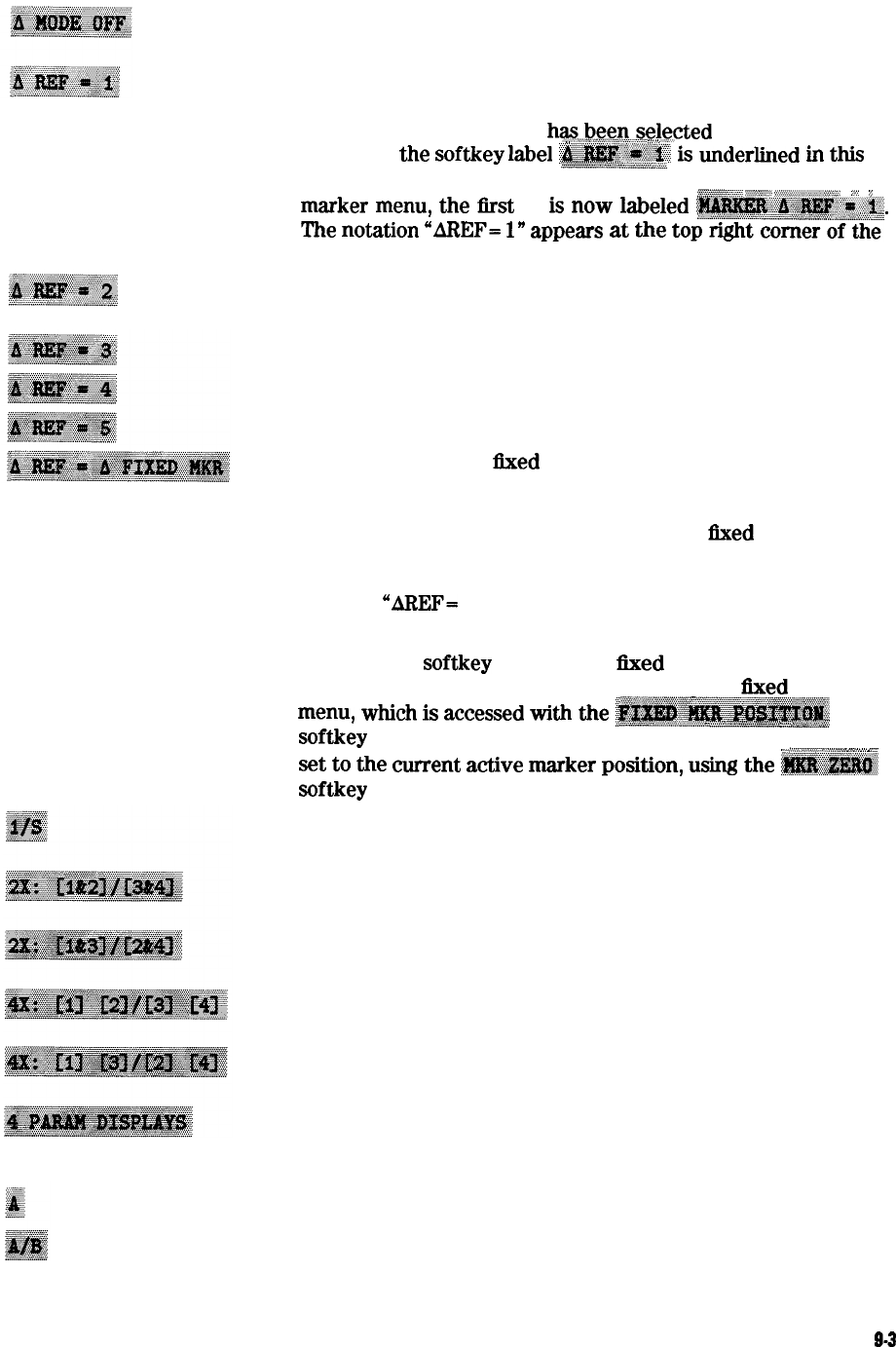
turns off the delta marker mode, so that the values displayed
for the active marker are absolute values.
establishes marker 1 as a reference. The active marker stimulus
and response values are then shown relative to this delta
reference. Once marker 1
has,~.~~.~...se!ected
as the delta
.,.
. . . . . . . . . .
j....
. . . . . .
reference, the
softkey
label
‘~~~~~~
is
underlined
h
t&
:.:.,.:.,.:.,.:.:.:.:.:.:.:.:.~.:.:~.~;:.:.:.~~.~:.~.,:...,:.~:.,.:.:.~~:.:.~:...:..
menu, and the marker menu is returned to the screen. In the
@f$fpgy
..:m*
.~~~~~~;;.;,~,~;,::~~~~,
:
,I.
y
marker
menu,
the first key
is
now
la&led
~~~~:~~~.~~.,-i~~~~~.
The
notation
“~EF=
1”
appears
at
the
to~~~~~~~~~~~~~
graticule.
makes marker 2 the delta reference. Active marker stimulus
and response values are then shown relative to this reference.
makes marker 3 the delta reference.
makes marker 4 the delta reference.
makes marker 5 the delta reference.
sets a user-specified
fixed
reference marker. The stimulus and
response values of the reference can be set arbitrarily, and can
be anywhere in the display area. Unlike markers 1 to 5, the
fixed marker need not be on the trace. The
ilxed
marker is
indicated by a small triangle A, and the active marker stimulus
and response values are shown relative to this point. The
notation
“AREF-
A” is displayed at the top right comer of the
graticule.
Pressing this softkey turns on the fixed marker. Its stimulus and
response values can then be changed using the
llxed
marker
.,
menu,
which
is
accessed
with
*e
~~~~~~~~~~~~
,.:.~.:.:.:.:.~.:.~.:.:.~.:.:.~:.,.:.:.:.:...:.;.:.:.:;.:.:.:.:.:.:.:.:.:.:.:
_
:::,:.::.:.~:.:.~:.:.:.:.:.:.~.~.~.:.~.:.:.~
,.,.,.,.,.,,
“i”,.:.,~~;~~:.,.
softkey described below. Alternatively, the fixed marker can be
.-_.;..;..
. . . . .../
,......,,...,.,,.,..,...,_
_
_;
_
_
_.
i
,._
set
to
the
current
adive
-ker
position,
using
the
~~~
softkey in the marker menu.
expresses the data in inverse S-parameter values, for use in
amplifier and oscillator design.
sets up a two-graticule display with channel 2 in the upper right
quadrant and channel 3 in the lower left quadrant.
sets up a two-graticule display with channel 3 in the upper right
quadrant and channel 2 in the lower left quadrant.
sets up a four-graticule display with channel 2 in the upper
right quadrant and channel 3 in the lower left quadrant.
sets up a four-graticule display with channel 3 in the upper
right quadrant and channel 2 in the lower left quadrant.
provides single-keystroke options to quickly set up
multiple-channel displays, and information on multiple-channel
displays
measures the absolute power amplitude at input A.
calculates and displays the complex ratio of input A to input B.
Key Definitions
3-3


