


How
!CRL*/LRM*
Calibration Works
The
TRL*/LRM*
calibration used in the HP 8753E relies on the characteristic impedance
of simple transmission lines rather than on a set of discrete impedance standards. Since
transmission lines are relatively easy to fabricate (in a microstrip, for example), the impedance
of these lines can be determined from the physical dimensions and substrate’s dielectric
constant.
TRL*
Error Model
[SAI
Error
Adapter
*
8 Error Terms
pm
2cd
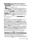
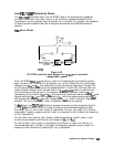
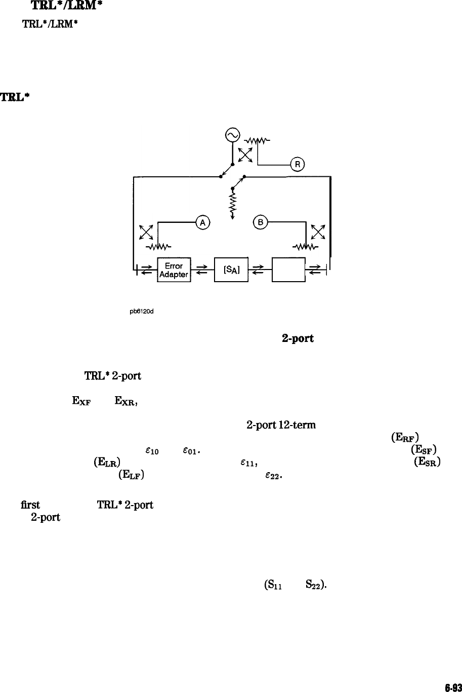
Figure 6-52.
HP 8753E functional block diagram for a
2-port error-corrected
measurement system
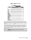
For an HP 8753E
TRL*
2-port
calibration, a total of 10 measurements are made to quantify
eight unknowns (not including the two isolation error terms). Assume the two transmission
leakage terms, Ezr and
EXR,
are measured using the conventional technique. The eight TRL
error terms are represented by the error adapters shown in Figure 6-52. Although this error
model is slightly different from the traditional Full
2-port
12-term
model, the conventional
error terms may be derived from it. For example, the forward reflection tracking
(Em)
is
represented by the product of
~10
and
&O1.
Also notice that the forward source match (Esr) and
reverse load match
(ELR)
are both represented by
~11,
while the reverse source match
(EsR)
and forward load match
(ELF)
are both represented by
&22.
In order to solve for these eight
unknown TRL error terms, eight linearly independent equations are required.
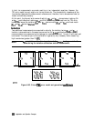
The
first
step in the
TRL*
2-port
calibration process is the same as the transmission step for
a Full
2-port
calibration. For the thru step, the test ports are connected together directly
(zero length thru) or with a short length of transmission line (non- zero length thru) and the
transmission frequency response and port match are measured in both directions by measuring
all four S-parameters.
For the reflect step, identical high reflection coefficient standards (typically open or short
circuits) are connected to each test port and measured (%I and
S22).
For the line step, a short length of transmission line (different in length from the thru) is
inserted between port 1 and port 2 and again the frequency response and port match are
measured in both directions by measuring all four S-parameters.
Application and Operation Concepts
6-93