


2.
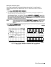
Select the type of polar marker you want from the following choices:
n
Choose
;&X#“?!&%
if you want to view the magnitude and the phase of the active marker.
.:/.:..
:.
The magnitude values appear in
units
and the phase values appear in degrees.
.
Choose
;.~~~~~~
if
you
witnt
to
view
the
logarithmic
magnitude
and
the
phase
of
the
. . . . . . . . . . . . . .
.
. . . . .
active marker. The magnitude values appear in
dE?
and the phase values appear in
degrees.
n
Choose
%@&tt;JjX$I$
if you want to view the real and imaginary pair, where the complex
data is separated into its real part and imaginary part. The analyzer shows the
first
marker value the real part (M cos
0),
and the second value is the imaginary part
(M sin
0,
where M=magnitude).
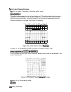
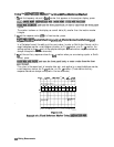
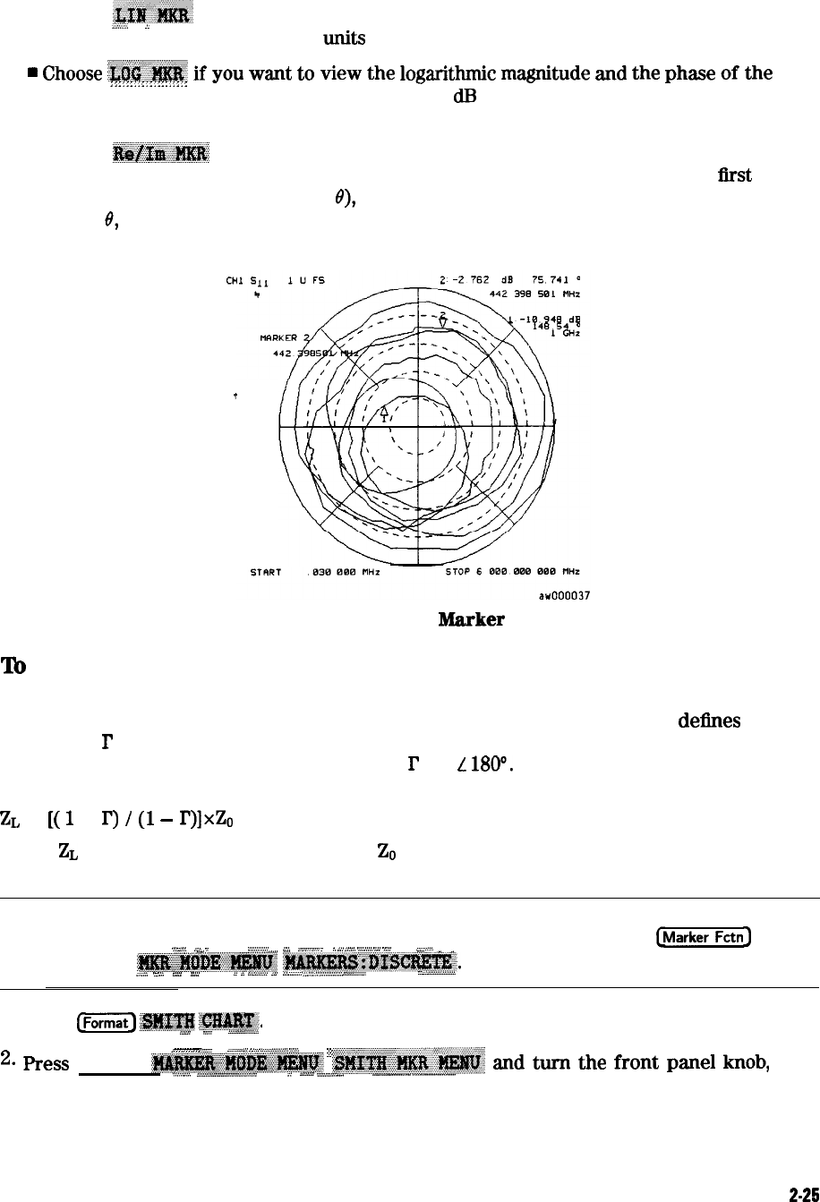
Figure
2-16. Example of a Log
Marker
in Polar
Format
t
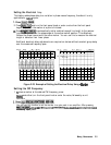
To
Use Smith Chart Markers
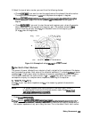
The amount of power reflected from a device is directly related to the impedance of the device
and the measuring system. Each value of the reflection coefficient (I’) uniquely
deties
a device
impedance;
r
= 0 only occurs when the device and analyzer impedance are exactly the same.
The reflection coefficient for a short circuit is:
r
= 1
L
BOO.
Every other value for I’ also
corresponds uniquely to a complex device impedance, according to the equation:
zL
=
[(
1
+
r)
I
(1
-
r)lxz,
where
ZL
is your test device impedance and
Z0
is the measuring system’s characteristic
impedance.
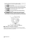
Note
For greater accuracy when using markers in the Smith chart format, it
is recommended to activate the discrete marker mode. Press
(j-1
. . . . . . . . . . . . . . . . . . . . . . . . . . . . . . . . . .
1....
;;.\
*/
.:
. . . . . . . . . . . . . . . . ..~.................
*..
“‘..T
i
.,
/,.
,,......A
c,.,.,.,.,
.,.a
..:.:
::.:.....
s..
. . . . . . . . . . . . . . . . . . . . . . .
_
,,
,,*;
,;
,,,,,,,,,,
_
. . . . . . .
_
., . . . . . ,.
~~~~~~~
~~~~~~.
..,.
.,.,.,
.
. . . . .
L...
,a..
. . . . . . . . . .
. ..A.. . . . . . . . .
..>>d
.
.
i:
.
. .
..A
. . . . ..A......
2
;;;
._...:
../
..i_ii
..A............_
.
.::
..:
:..:::::.::.::::.
1.
Press
(jjj
~~#@j?IjI
‘j3JU&&.
. . . . . . . . . . . . . . .
. . . . . . . . . . . . . . . . . . . . . . . . . . . . . . . . .
.:..:..:
. . .
. . .
.
.::::
. . . .
.
~~~.............~.;;;.i
/
.
.
.
.
.
.
.
.
.
.
.
.
.
.
.
.
.
.
.
.
.
.
/
~~:::::
.
.
.
.
.. .
.
.
;<.:
.
.
.
.
.
:.y,., ..::::
::.<.z
.;
:.....
.::~:...::~:::::~:p
.;
.
.
.
.
.
.
.
.
.
.
.
.
.
.
.
.
:,::
:;,
::-:<::<:
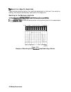
2.
Ress
(Marker]
~~~~~~~~~
~~~~~~~~
ad
turn
the
front
panel
knob, or
.,.,,.,.vii
. . . . . .
~;;~~.....................................~_/......
. . . . . . . . . . . . . . . . . . . . . . . . . . . . . . ..i . . . . . . . . A...::>..; .
.
. . . .
. . . . .
...............,..i
.,..
.._.................. ,........................
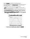
enter a value from the front panel keypad to read the resistive and reactive components of
the complex impedance at any point along the trace. This is the default Smith chart marker.
Making Measurements
2-25