


Attenuation at Mixer Ports
Mismatch between the instruments, cables, and mixer introduces errors in the measurement
that you cannot remove with a frequency response calibration. You can reduce the mismatch
by using high quality attenuators as close to the mixer under test as possible.
When characterizing linear devices, you can use vector accuracy enhancement (measurement
calibration) to mathematically remove all systematic errors from the measurement, including
source and load mismatches. This is not possible when the device you are characterizing is a
mixer operating over multiple frequency ranges: therefore, source and load mismatches are not
corrected for and will add to overall measurement uncertainty.
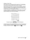
To reduce the measurement errors associated with the interaction between mixer port matches
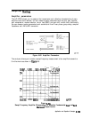
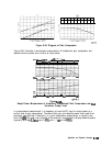
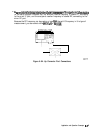
and system port matches, you can place attenuators at all of the mixer’s ports. Figure 6-89
shows a plot of swept conversion loss where no attenuation at mixer ports was used. The
ripple versus frequency is due to source and load mismatches+
pg6162-c
Figure 6-89.
Conversion Loss versus Output Frequency Without Attenuators at
Mixer Ports
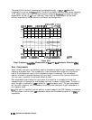
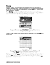
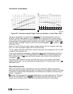
In contrast, Figure 6-91 made use of appropriate attenuation at all mixer ports You should give
extra care to the selection of the attenuator located at the mixer’s IF port to avoid overdriving
the receiver. For best results, choose the value of this attenuator so #at the power incident on
the analyzer’s R channel port is less than -10
dBm
and greater than -35
dRm.
Application and Operation Concepts
B-1
68