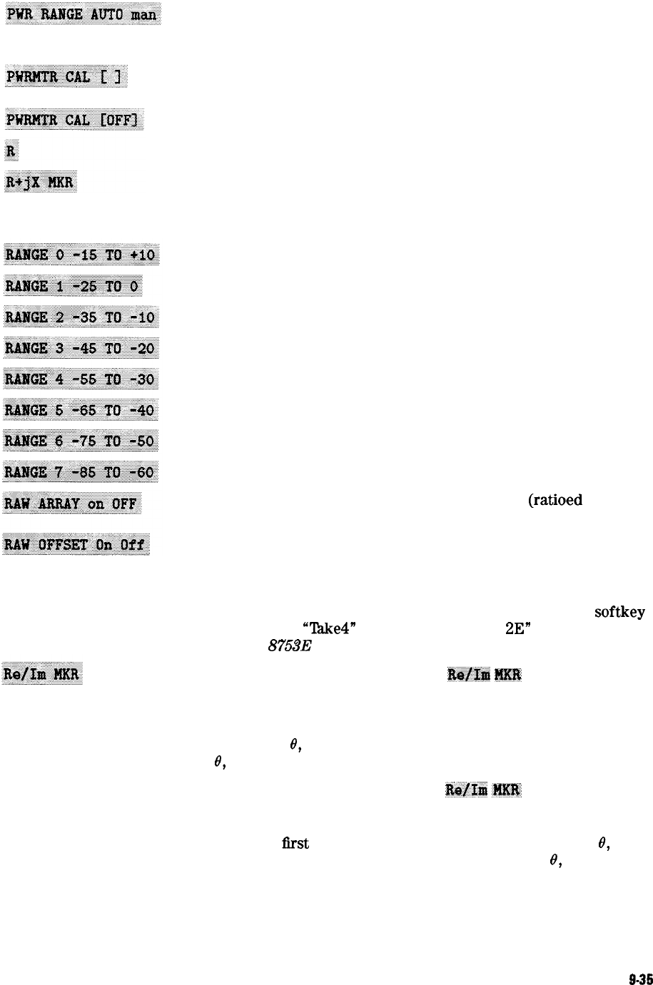
toggles the power range mode between auto and manual. Auto
mode selects the power range based on the power selected.
Manual mode limits power entry to within the selected range.
leads to the power meter calibration menu which provides two
types of power meter calibration, continuous and single-sample.
turns off power meter calibration.
measures the absolute power amplitude at input R.
converts the active marker values into rectangular form. The
complex impedance values of the active marker are displayed in
terms of resistance, reactance, and equivalent capacitance or
inductance. This is the default Smith chart marker.
selects power range 0 when in manual power range.
selects power range 1 when in manual power range.
selects power range 2 when in manual power range.
selects power range 3 when in manual power range.
selects power range 4 when in manual power range.
selects power range 5 when in manual power range.
selects power range 6 when in manual power range.
selects power range 7 when in manual power range.
specifies whether or not to store the raw data (ratioed and
averaged) on disk with the instrument state.
selects whether sampler and attenuator offsets are ON or OFT
By selecting raw offsets OFT, a full two port error correction
can be performed without including the effects of the offsets.
It also saves substantial time at recalls and during frequency
changes. Raw offsets follow the channel coupling. This softkey
is used with
“‘lhke4”
mode. See “Example
2E”
in Chapter 2 of
the
HP 8753E Programmer’s Guide.
when in the smith marker menu,
X&lx&
m
displays the
values of the active marker on a Smith chart as a real and
imaginary pair The complex data is separated into its real part
and imaginary part. The first marker value given is the real
part M cos
0,
and the second value is the imaginary part M sin
0,
where M = magnitude.
When in the polar marker menu,
l$e&tl
.Ml$
displays the
values of the active marker as a real and imaginary pair The
complex data is separated into its real part and imaginary
part. The
first
marker value given is the real part M cos
0,
and the second value is the imaginary part M sin
0,
where
M = magnitude.
Key Definitions
9-35


