


H=2
H=3
Hld
PC
PC?
F?
Pl
PRltl
Smo
tsH
Harmonic mode is on, and the second harmonic is being measured (harmonics
Option 002 only). (See “Analyzer Options Available” later in this chapter.)
Harmonic mode is on, and the third harmonic is being measured (harmonics
Option 002 only). (See “Analyzer Options Available” later in this chapter.)
Hold sweep. (See
:@&I$
in Chapter 9, “Key Definitions.“)
Waiting for manual trigger.
Power meter calibration is on. (For power meter calibration procedures, refer
to Chapter 5,
“Optimlzmg
Measurement Results.
n
For power meter calibration
theory, refer to Chapter 6, “Application and Operation Concepts. “)
The analyzer’s source could not be set to the desired level, following a power
meter calibration. (For power meter calibration procedures, refer to Chapter 5,
“Optimizing Measurement Results.” For power meter calibration theory, refer to
Chapter 6, “Application and Operation Concepts
“)
Source power is unleveled at start or stop of sweep. (Refer to the
HP
8753E
Network
An.uZgm
Semrice
Guide
for troubleshooting.)
Source power has been automatically set to
minimum, due to receiver overload.
.i............/
..
i
..i
i
(See
J%I@
in Chapter 9, “Key Definitions. “)
-
Power range is in manual mode.
Trace smoothing is on. (See
“0”
in Chapter 9, “Key Dellnitions.“)
Indicates that the test set hold mode is engaged.
That is, a mode of operation is selected which would cause repeated switching of
the
step
attenuator.
This
hold
mode
may
be
overridden.
See
~~~~~~~~~
. . . . . .
.:.:.:,:.:.:.:.
or
~~~~~~~~~~~
h
Chapter
9,
“Key
Definitions”
)
_,_/,,,/,,
;.;..~,.~,.~,.~.~~;~,:~:~~~~;.:~~:.:;~~~~~~~~:.:~.,.~:
/,,,.
:.:.,.:.:.:
.,,,.
:.:.:
.,,,....
:.:-_
./
Fast sweep indicator. This symbol is displayed
in
the status notation block when
sweep time is less than 1.0 second. When sweep time is greater than 1.0 second,
this symbol moves along the displayed trace.
Source parameters changed: measured data in doubt until a complete fresh
sweep has been taken.
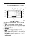
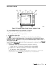
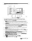
4.
Active
Entry
Area.
This displays the active function and its current value.
5.
Message
Area.
This displays prompts or error messages.
6.
Title.
This is a descriptive alphanumeric string title that you
define
and enter through
an attached keyboard or as described in Chapter 4, “Printing, Plotting, and Saving
Measurement Results.
n
7.
Active Channel. This
is the label for the active channel, selected with the
@Gily(Chan
3) and
w(Chan
4) keys. If multiple channels are overlaid, the labels will appear in
this area. The active channel is denoted by a rectangle around the channel number.
For
multiple-graticule
displays, the channel information labels will be in the same relative
position for each graticule.
Note
The label of the active channel is enclosed in a rectangle to differentiate it
from inactive channels.
HP
6753E
Description and Options
l-6