


The
TRL
Calibration Procedure
Requirements for
TRL
Standards
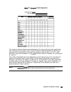
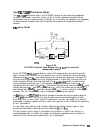
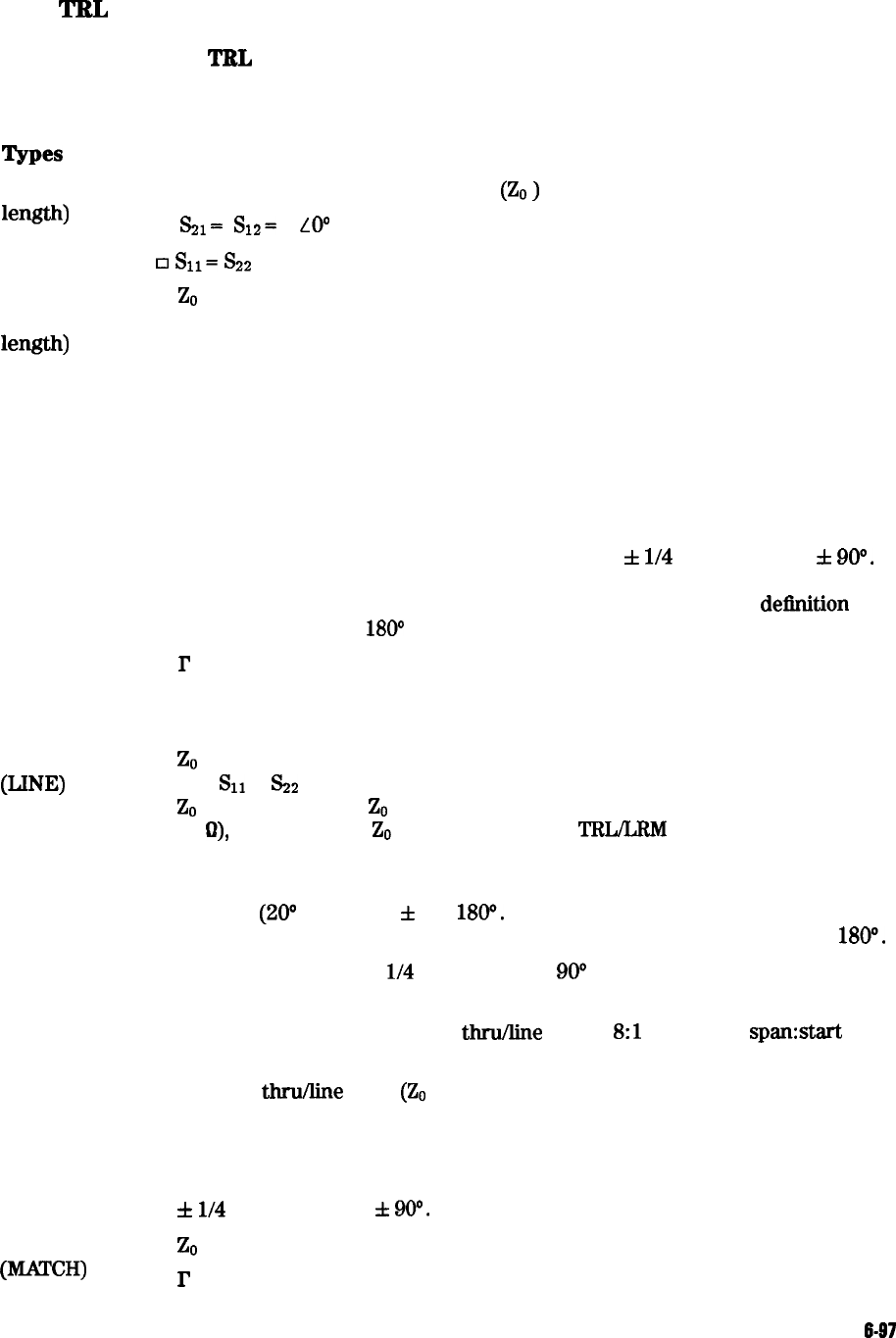
When building a set of TRL standards for a microstrip or fixture environment, the requirements
for each of these standard types must be satisfied.
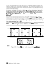
Types
Requirements
THRU (Zero
length)
q
No loss. Characteristic impedance
(ZO
)
need not be known.
q
&?I=
S12=
1
LO0
0
s11=
s22
= 0
THRU
(Non-zero
length)
REFLECT
LINE/MATCH
WW
LINE/MATCH
(WCH)
q
ZO
of the thru must be the same as the line. (If they are not the same, the
average impedance is used.)
q
Attenuation of the thru need not be known.
q
If the thru is used to set the reference plane, the insertion phase or
electrical length must be well-known and specified. If a non-zero length
thru is specified to have zero delay, the reference plane is established in the
middle of the thru, resulting in phase errors during measurement of
devices.
q
Reflection coefficient (I’ ) magnitude is optimally 1.0, but need not be
known.
q
Phase of I’ must known and specified to within
f
l/4
wavelength or
f
90’.
During computation of the error model, the root choice in the solution of a
quadratic equation is based on the reflection data. An error in
delinition
would show up as a
180°
error in the measured phase.
q
P
must be identical on both ports.
q
If the reflect is used to set the reference plane, the phase response must be
well-known and specified.
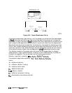
q
Z0
of the line establishes the reference impedance of the measurement
(i.e.
Sll
=
&2
= 0). The calibration impedance is defined to be the same as
Z0
of the line. If the
ZO
is known but not the desired value (i.e., not equal to
50
a),
the SYSTEMS
ZO
selection under the
TRL/LRM
options menu is used.
q
Insertion phase of the line must not be the same as the thru (zero length
or non-zero length). The difference between the thru and line must be
between
(20°
and 1600)
f
n x
1800.
Measurement uncertainty will increase
significantly when the
insertion
phase nears 0 or an integer multiple of
180”.
q
Optimal line length is
l/4
wavelength or
90”
of insertion phase relative to
the thru at the middle of the desired frequency span.
q
Usable bandwidth for a single
thru/Iine
pair is
8:l
(frequency spanstart
frequency).
q
Multiple
thru/line
pairs
(ZO
assumed identical) can be used to extend the
bandwidth to the extent transmission lines are available.
q
Attenuation of the line need not be known.
q
Insertion phase must be known and specified within
f
l/4
wavelength or
f
90”.
q
Z0
of the match establishes the reference impedance of the measurement.
q
P
must be identical on both ports
Application and Operation Concepts
6-97