


To
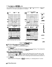
Divide Measurement Data by the Memory Trace
You can use this feature for ratio comparison of two traces, for example, measurements of gain
or attenuation.
1. You must have already stored a data trace to the active channel memory, as described in
“To
Save a Data Trace to the Display Memory.”
..“’
:.
2. Press (Display)
~~~~~~
to divide the data by the memory.
il...
.:
i.i
.:..
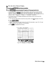
The analyzer normalizes the data to the memory, and shows the results
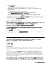
To Subtract the Memory Trace from the Measurement Data Trace
You can use this feature for storing a measured vector error, for example, directivity. Then,
you can later subtract it from the device measurement.
1. You must have already stored a data trace to the active channel memory, as described in
“‘lb
Save a Data Trace to the Display Memory.
ff
2.
press
(jj
~~~ar~~~~,
to
subtract
the
memory
from
the
measurement
data.
;;;;A.::..:
..:.....,...:....
. . .
2..
The analyzer performs a vector subtraction on the complex data.
‘RI
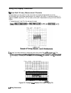
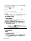
Ratio Measurements in Channel 1 and 2
You may want to use this feature when making amplifier measurements to produce a trace that
represents gain compression. For example, with the channels uncoupled, you can increase the
power for channel 2 while channel 1 remains unchanged. This will allow you to observe the
gain compression on channel 2.
,,.,.,....;
.,.,,.,.,.,.,.....,.,..,.;
. . . . . . . . . . . . .
1.
Press
lMenJ
~~~~~~~~~~~~
to
mcouple
the
c.,annels.
..i
.
..........
. . .
. . .
.::
.: i.:::........;.;~
i
..
. . . . . . . .
.:::
i.......i
.A..
2. Make sure that both channels must have the same number of points.
a.
press
(~,
[=,
~~~~~~~~~~
and
notice
the
number
of
points
setting,
shown
on the analyzer display.
. . . .
..I.............................,.,.,..:
.,.,
p
,.
,,,,.
‘I .&
...:.,:::::~
....
..:::.:
.
...:
,:,:,
:-;,:::::.:
b. Press
@iZZ)
[Menu_)
~~~~~~~~~:~~~~~ and enter the same value that you observed for
,,a...
. . .
. . . . . . .
i ,......
.::::.:..
.A.................
~~~.~~.
.
. . . . .
.:.,.;.;.,;;;..;;;.i
. . .
..
.
.::::::
the channel 1 setting.
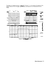
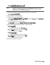
3.
Press
~~isp,ay,
~~~
~~~~~~~,~~~~
to
ratio
channels
l
and
2,
and
put
the
results
in
the
,.;;
. . . . . . . .
;;:
.A....
LL.;.
;. . . . . .
1
. .
..A
T.T
. . .
.._....
. . . . . . . . . . . . . . . . .
L.~~~~.,~...,..,~~~
.............i
channel 2 data array. This ratio is applied to the complex data.
4. Refer to Chapter “Measuring Gain Compression” for the procedure on identifying the 1
dB
compression point.
2-8
Making Measurements