


Note
In the following two steps, calibration data is recalled, not instrument states.
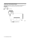
10.
kom
the disk directory, choose the file associated with the port 1 error correction, then
. . . . . . .
i
press
~~~:~~~~~~~~..
.;;s’
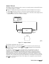
11. When this is complete, choose the
hle
for the port 2 error correction and press
~~~“::9
P
I’...
‘-‘~+‘~::.+;:I’
;&%&~$fggg
$2
.
12-
When complete, press
~~~‘.
13. Enter the value of the electrical delay of adapter
A3.
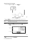
15.
Press
~~~~~~~~~~
to
complete
the
technique
for
cd&ating
the
new
errOr
../............,
. . .
...&..
:.:
.:..:....
L>>:.::<.::<.
. . . . . . .
:..
:.......>,..:5:...
coefficients and overwrite the current active calibration set in use.
This process uses up an internal memory register. The calibration in this register is
not
the calibration created by adapter removal, rather it is a “scratch” calibration. You may
wish to delete the register, or re-save the new calibration in this register as shown in the
following step.
. . . . . . . . . . . . . . . . . . . . . . . . .
_
...........
;,.;.;
_
,,..
:.:.
s
.:
;
..*i
16.
‘fb
save the rest&s of the new
cd
set,
press
Cv)
:~~~~..~~~~~
~~~~~~~~
i,.,../.~~~~ .A..............
.T
..:.:: .:
;..x
. . . .
::.;..u
/ii
. . . . . . . . . . . . . . . . . . . . . . . . . . . . . . . . .
.
. . . . . . . . .
. . . . . . . . . . .
.
. .
:....:
:..,...
I........
/
. . .
. . . . . ;::...w;; .. . . . . .
:.A,.::
ii
.::..
g&&#
~~~~~~~.
:::.
.:.
.x.
,,,, ,.
,:
. . . . . . . .
..-...............
i.~::.~::::
~:::::..~...;;....:..
i. i.;m
‘:‘..:
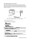
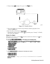
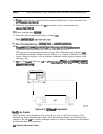
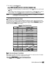
NETWORK ANALYZER
DUT
pg649e
Figure 5-14.
Cklibrated
Measurement
Verify
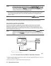
the Results
Since the effect of the adapter has been removed, it is easy to verify the accuracy of the
technique by simply measuring the adapter itself. Because the adapter was used during the
creation of the two
cal
sets, and the technique removes its effects, measurement of the adapter
itself should show the S-parameters.
544
Optimizing Measurement Results