


:
;,.*'p..;;..'..:'~
',,;.
../
.'".
~~~~~~~:~~~~~~.
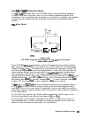
allows you to specify energy loss, due to skin effect, along a one-way length of
.
T
.,.........
.::
.A..
..s . . . . . . . . . . . .. . .
/.::
.
. .
. . .
. . .
coax offset. The value of loss is entered as ohms/nanosecond (or
Giga
ohms/second) at 1
GHz.
(Such losses are negligible in waveguide, so enter 0 as the loss offset.)
~&‘?lW&~;~@~.
allows you to specify the characteristic impedance of the coax offset. (Note:
..i
_..............;.....
/
This is not the impedance of the standard itself.) For waveguide, the offset impedance as
well as the system ZO must always be set to
10.
;
i
~:~~~~~~~~~~~~’
allows
you
to
define
the
lowest
frequency
at
which
the
standard
s>:<.:
../..
:..::...;~.::..:
/..
~~~~~.:,~.~.:.:..;”
,...
::..-
. . . .
::.:
. . . . .
;..:.&
. . . .. .
::..<.:<...:
.
. . . . .
. .
. . .
.
;,>:.
can be used during measurement calibration. In waveguide, this must be the lower cutoff
frequency of the standard, so that the analyzer can calculate dispersive effects correctly (see
ii
:
;,
,/“;:;yw:y
,,:~;;~;”
,ii.
~~~~~~~~~
above).
,:p,.:.<,.:.;
..
.,
::
.,
.,
;:;.:.:.+..:.:.:
_:
~~,~~~~~~~
allows you to
deilne
the highest frequency at which the standard can
i
:..;....;.;.~..~~~.
. . . . . . . .
~~.............::.;;...i..
.A..
. .
..A
.._
I
.
..u.i
i
. . . . . . . . .
i
be used during measurement calibration. In waveguide, this is normally the upper cutoff
frequency of the standard.
~~~
defines
the
s-&d
(and
the
offset)
pi
co&~.
‘I&is
causes
the
analyzer
to
ame
i;;;
. . .. . . . . . . . :...;..:;
:,.
ilL,.,,
linear phase response in any offsets.
_
. . . . . . . . . . . . . . . . . . . . . . . . .
,.
.,.
. . . .
_
. . . . .
~~~~~~
defines the standard (and the offset) as rectangular waveguide. This causes the
7:
Label Standard
Menu
This menu allows you to label (reference) individual standards during the menu-driven
measurement
cahbration
sequence. The labels are
user-de&table
using a character set shown
on the display that includes letters, numbers, and some symbols, and they may be up to ten
characters long. The analyzer will prompt you to connect standards using these labels, so they
should be
meaningfuI
to you, and distinct for each standard.
By convention, when sexed connector standards are labeled male (m) or female (f), the
designation refers to the test port connector sex, not the connector sex of the standard.
Specify
Class Menu
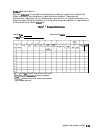
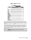
Once a standard has been defined, it must be assigned to a standard “class.” This is a group of
from one to seven standards that is required to calibrate for a single error term. The standards
within a single class can be assigned to the locations listed in
‘Ihble
6-6 according to their
standard reference numbers.
A class often consists of a single standard, but may be composed of more than one standard if
band-limited standards are used. For example, if there were two load standards
-
a fixed load
for low frequencies, and a sliding load for high frequencies
-
then that class would have two
standards.
6-88 Application and Operation Concepts