


Each standard must be identified as one of five “types”: open, short, load,
delay/thru,
or
arbitrary impedance.
After a standard number is entered, selection of the standard type will present one of five
menus for entering the electrical characteristics (model coefficients) corresponding to that
standard type, such as
&&.
These menus are tailored to the current type,
so
that
only
characteristics applicable to the standard type can be modified.
The following is a description of the softkeys located within the
define
standard menu:
“‘...
(’
,,,:
y
.
:jX%@
defines the standard type as an open, used for calibrating reflection measurements.
TT
,,..
.:.,,i:.i
Opens
are assigned a terminal impedance of
infinite
ohms, but delay and loss offsets may
still be added. Pressing this key also brings up a menu for
defining
the open, including its
capacitance.
As a reflection standard, an open termination offers the advantage of broadband frequency
coverage. At RF and microwave frequencies, however, an open rarely has perfect reflection
characteristics because fringing capacitance effects cause phase shift that varies with
frequency. This can be observed in measuring an open termination after calibration, when
an arc in the lower right circumference of the Smith chart indicates capacitive reactance.
These effects are impossible to eliminate, but the calibration kit models include the open
termination capacitance at all frequencies for compatible calibration kits. The capacitance
model is a cubic polynomial, as a function of frequency, where the polynomial coefficients
are user-deflnable. The capacitance model equation is:
C = (CO) + (Cl x
F)
+
(C2
x
F2)
+
(C3
x
P)
where F is the measurement frequency.
The terms in the equation are defined with the specify open menu as follows:
..:.
:
%J&
allows you to enter the CO term, which is the constant term of the cubic polynomial
and is scaled by
lo-l5
Farads
..iiii.l
i:
?$&:
allows you to enter the Cl term, expressed in
F/Hz
(Farads/Hz) and scaled by
10V2’.
;#$ allows you to enter the
C2
term, expressed in
F/Hz2
and scaled by
10-36.
&:
allows you to enter the
C3
term, expressed in
F/H23
and scaled by
10-45.
/.........;..;
i....
%....
._
_
.,.,.._
F.,
/
n
###$I@
defines
the standard type as a short, for calibrating reflection measurements Shorts
.A....,,.
.:,.:::.../
,....,.
/.s..s . . .
..A
. . . .
are assigned a terminal impedance of 0 ohms, but delay and loss offsets may still be added.
.
~~~~~
defines
me
sm,-Jxd
type
w
a
lo&
(te-mjnacon).
Lo&
are
assigned
a
teeal
impedance equal to the system characteristic impedance ZO, but delay and loss offsets
may still be added. If the load impedance is not ZO, use the arbitrary impedance standard
deiinition.
. . .
/........;../i
;J@&f&
defies
the
lo&
u
a
jjxed
(not sliding) load.
,~~~~~~~.
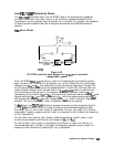
defines the load as a sliding load. When such a load is measured during
calibration, the analyzer will prompt for several load positions, and calculate the ideal load
value from it.
n
~~~~~~
deilnes
the standard type as
a
transmission line of
specified
length, for
calibrating transmission measurements.
6-66 Application and Operation Concepts