


NETWORK
ANALYZER
BIAS TEE
BIAS TEE
i_:#j-+-p
0
10
dB
10
dB
ATTENUATOR
FIXTURE
ATTENUATOR
pg640e
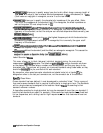
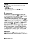
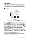
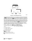
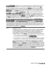
Figure 6-54. Typical Measurement Set up
If the device measurement requires bias, it will be necessary to add external bias tees between
the
iixed
attenuators and the fixture. The internal bias tees of the analyzer will not pass the
bias properly through the external fixed attenuators, Be sure to calibrate with the external bias
tees in place (no bias applied during calibration) to remove their effect from the measurement.
Because the bias tees must be placed after the attenuators, they essentially become part of the
fixture. Their mismatch effects are the same for source match and load match, so the TRL CAL
routine will correct for their effects Although the fixed attenuators improve the raw mismatch
of the network analyzer system, they also degrade the overah measurement dynamic range.
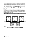
This effective mismatch of the system after calibration has the biggest effect on reflection
measurements of highly reflective devices, Likewise, for well matched devices, the effects of
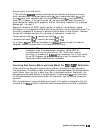
mismatch are negligible. This can be shown by the following approximation:
Reflection magnitude uncertainty
=
ED
+
ER&I
+
WW2
+ E~s21S12
Transmission magnitude uncertainty =
EX
+
E&l
+
EsSllSzl
+
E&&l
where:
En = effective directivity
En = effective reflection tracking
Es = effective source match
EL
= effective load match
Ex
=
effective crosstalk
E,-r
= effective transmission tracking
&,,
= S-parameters of the device under test
6-86
Application and Operetion Concepts