


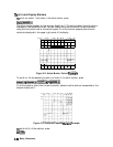
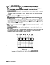
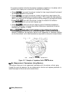
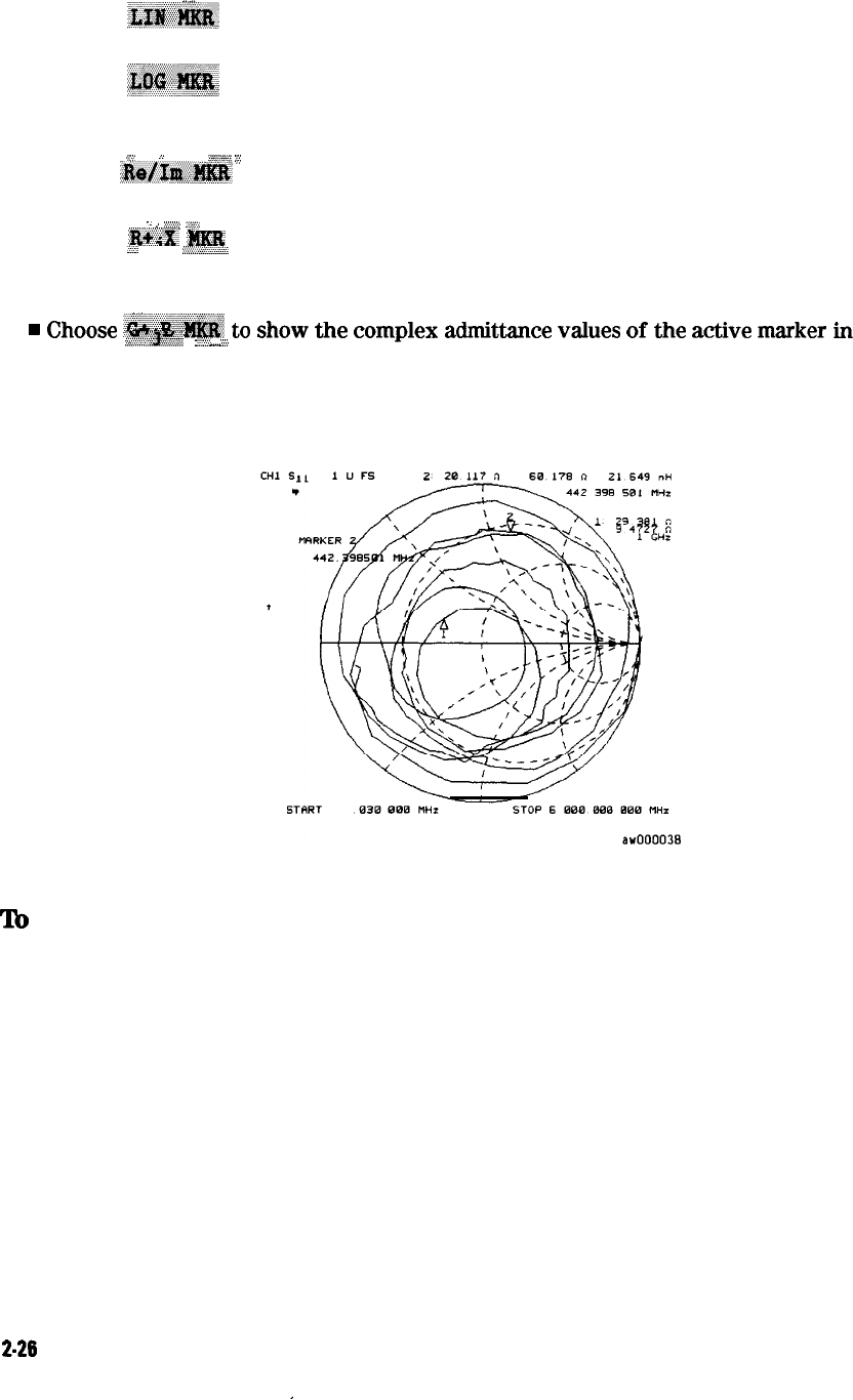
The marker annotation tells that the complex impedance is capacitive in the bottom half of
the Smith chart display and is inductive in the top half of the display.
,/
“.’
n
Choose .X&@I#& if you want the analyzer to show the linear magnitude and the phase of
the reflection coefficient at the marker.
n
Choose
~~~~~~~~
if you want the analyzer to show the logarithmic magnitude and the
phase of the reflection coefficient at the active marker. This is useful as a fast method of
obtaining a reading of the log magnitude value without changing to log magnitude format.
I’
.i
ii
..><y%%,;;
.s,:
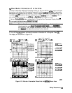
. Choose
:&$&G@K
if you want the analyzer to show the values of the reflection
coefficient at the marker as a real and imaginary pair.
.
.
,.
..y.::.,.
,,“‘,
n
Choose
,
‘IEZ$
to show the real and imaginary parts of the device impedance at
:...:
3
:.:.:..:~L:+..
the marker. Also shown is the equivalent series inductance or capacitance (the series
resistance and reactance, in ohms).
.
.
.
_
.,
.
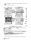
Choose
.,~~~;~~~
to
show
the
complex
admittance
values
of
l&e
a&&e
marker
h
:d;$;:.:&~*+~+
.
...,:.;
,,,,,
a.:
rectangular form. The active marker values are displayed in terms of conductance (in
Siemens), susceptance, and equivalent parallel circuit capacitance or inductance. Siemens
are the international unit of admittance and are equivalent to mhos (the inverse of ohms).
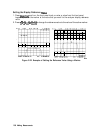
Figure 2-17. Example of Impedance Smith Chart Markers
‘lb
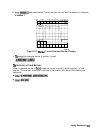
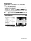
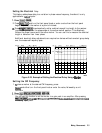
Set Measurement Parameters Using Markers
The analyzer allows you to set measurement parameters with the markers, without going
through the usual key sequence. You can change certain stimulus and response parameters to
make them equal to the current active marker value.
2-26
Making Measurements