


3.
Press
(ZiJ
~~~~~
and enter the test port power level that you want the analyzer
/
to maintain at the input to your test device. Compensate for the power loss of the power
splitter or directional coupler in the setup.
4. If you want the analyzer to make more than one power measurement at each frequency
data
point,
press
~~~~~~~.~~~~~”
o
Ixl)
(where
n
=
the
number
of
desired
..: . . .
..c .i
i/
. . . . .
L.3
.:....
.I?
iterations).
If you increase the number of readings, the power meter correction time will substantially
increase.
:.
.:
::.
i.
,;
,,
;
.:
/.~~~~~~~~.:~~~~..~~~~~;~.:;~.~:.
‘<.
.(.
. . .::.:.
5.
Press
@
,~~~~~~
#&@&f$m.
,~~~~~~.~~~~
to
a&iv&e
the
power
meter
i
......~~~~.~~~..~~...;...i
. . . . . . . . . .
s......i
i.i....,.....
,...., ,,, ,.,
. ../.: . . . . . . . . . . . . ..>......... . . . . .
s.2
. . . . . .
s.,.
,...
;...:
..T.:‘...<<..
. . . . . . . .
. . .../. . . . . . . ..//...................../.
correction.
To
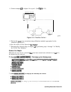
Calibrate the Analyzer Receiver to Measure Absolute Power
You can use the power meter calibration as a reference to calibrate the analyzer receiver to
accurately measure absolute power. The following procedure shows you how to calibrate the
receiver to any power level.
1.
2.
3.
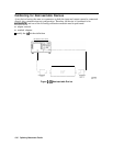
Set the analyzer test port power to the desired level:
.,...
_
,..
,.,
_
IMenu)
1~~~~~
(enter power
level)
Ixl)
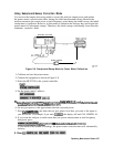
Connect the power sensor to the analyzer test port 1.
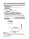
To apply the one sweep mode, press:
Note
Because power meter calibration requires a
longer
sweep time, you may want
. . . . . . . . . . . . . . . . . . . . . . . . . .
.:...
.:..:. ..:::.. ,.
_
_
_
to reduce the number of points before pressing
~~~~~:~~~~~.
After the
i.;;;;;;;;;;..;~~.;..;;;;;;;;..........:.....;...
. . . . .
. . .
i
;A%%%
. . .
..A
.:.x:
ii
A...u.s.;u;;;i
..,.,.
i.
power meter calibration is finished, return the number of points to its original
value and the analyzer will automatically interpolate this calibration.
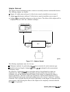
The status notation PC will appear on the analyzer display. Port 1 is now a calibrated source
of power.
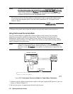
4. Connect the test port 1 output to the test port 2 input.
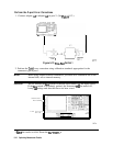
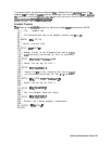
5. Choose a non-ratioed measurement by pressing:
This sets the source at PORT 1, and the measurement receiver to PORT 2, or input port B.
6.
‘Ib
perform a receiver error-correction, press:
The receiver channel now measures power to a characteristic accuracy of 0.35
dB
or better.
The accuracy depends on the match of the power meter, the source, and the receiver.
Optimizing Measurement Results 5-39