


‘able
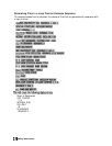
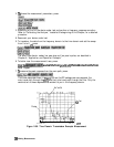
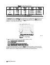
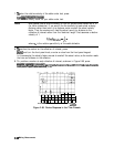
2-2. Gate Characteristics
Gate
Pas&and Sidelobe
cntoff
shape
Eipple
LeVdS
Gate Span Minimum
zto.1
dEs
-48dEt
lA/Freq
Span
Normal 50.1
dB
-68
dB
2.8/Freq
Span
Wide
fO.l
dB
-57
dB
4.4Freq Span
MaXimUIlI
fO.O1
dB
-70
dB 12.7Preq
Span
I
NOTE: With 1601 frequency points, gating is available only
in
the bandpass mode.
Gate
spfm
B.S/Freq
Span
6.6/Freq
Span
8.8Preq
Span
26.4Freq
Span
I
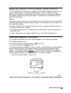
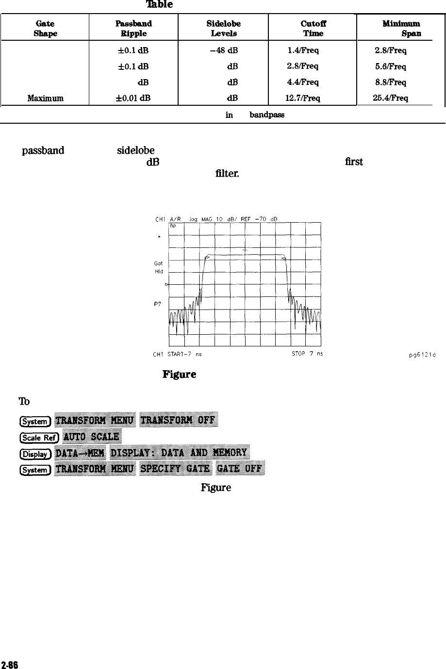
The
passband
ripple and
sidelobe
levels are descriptive of the gate shape. The cutoff time is the
time between the stop time (-6
dB
on the filter skirt) and the peak of the
first
sidelobe, and
is equal on the left and right side skirts of the
hlter.
Because the minimum gate span has no
passband, it is just twice the cutoff time.
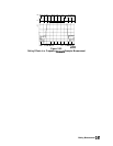
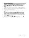
CHl
A/R
log
MAG
10
dB/
REF
-70
dB
P?
CHl
START-7
ns
STOP
7
ns
pg6121d
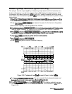
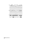
Fiiure
2-61. Gate Shape
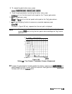
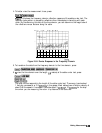
13.
‘lb
see the effect of the gating in the frequency domain, press:
This places the gated response in memory.
F’igure
2-62 shows the effect of removing the RF
leakage and the triple travel signal path using gating. By transforming back to the frequency
domain, we see that this design change would yield better out-of-band rejection.
2-86 Making Measurements