


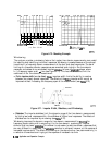
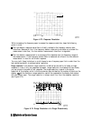
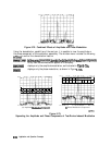
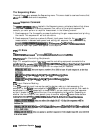

Figure 6-78. Combined Effects of Amplitude and Phase Modulation
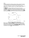
Using the demodulation capabilities of the analyzer, it is possible to view the amplitude or
the phase component of the modulation separately. The window menu includes the following
softkeys to control the demodulation feature:
~~~~~;~~~~~
.i: i
..:.
i
c..........
i
ii ii . . . . . . . . . . . . . .
L.:...
:
I....
is
the
normal
preset
state,
h
which
both
the
mpl&&
ad
phase
components
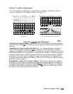
of any test device modulation appear on the display.
~~~~~~
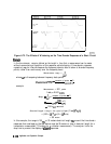
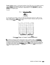
displays only the amplitude modulation, as illustrated in
F’igure
6-79a.
. . . . . .
.:..,
.,.,.;/,-,.,.,.
,,..A
~~~
. . . . . . .
displays only the phase modulation, as shown in Figure
6-79b.
1
i
i
i
i
iii
i
i
i
i
I
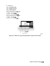
(a) Amplitude
Modulation
Component
(b)
Phase Modulation Component
Figure 6-79.
Separating the Amplitude and Phase Components of Test-Device-Induced Modulation
6-144
Application and Operation Concepts