


Making Accurate Measurements of Electrically Long Devices
A device with a long electrical delay, such as a long length of cable or a SAW
lllter,
presents
some unusual measurement problems to a network analyzer operating in swept frequency
mode. Often the measured response is dependent on the analyzer’s sweep time, and incorrect
data may be obtained. At faster sweep rates, the magnitude of the response may seem to drop
and look distorted, while at slower sweep rates it looks correct. The results may indicate that a
cable has more loss than it truly does, or that a
filter
has some unusual ripple in the
passband
which isn’t really there.
This section describes the cause of this behavior, and how to accurately measure these
electrically long devices.
The Cause of Measurement Problems
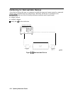
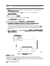
When using a vector network analyzer to measure a device that has a long electrical delay
(AT), the device’s time delay causes a frequency shift between its input and output signals The
frequency shift,
AP,
equals the product of the sweep rate and the time delay:
AF’=
dP/dt
*
AT
Since frequency is changing with time as the analyzer sweeps, the time delay of the DUT
causes a frequency offset between its input and output. In the analyzer receiver, the test and
reference input signals will differ in frequency by
AF’.
Because the test signal frequency is
slightly different than the receiver frequency, the analyzer will err in measuring its magnitude
or phase. The faster the analyzer’s sweep rate, the larger
AF’
becomes, and the larger the error
in the test channel.
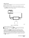
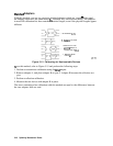
The HP 8753E network analyzers do not sweep at a constant rate. The frequency range is
covered in several bands, and the sweep rate may be different in each band. So if an operator
sets up a broadband sweep with the
minimum sweep time, the error in measuring a long device
will be different in each band, and the data will be discontinuous at each band edge. This can
produce confusing results which make it difficult to determine the true response of the device.
To
Improve Measurement Results
‘lb
reduce the error in these measurements, the frequency shift, AF, must be reduced.
AF’
can
be reduced by using the following three methods:
n decreasing the sweep rate
w
decreasing the time delay (AT)
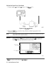
Decreasing the Sweep Rate
The sweep rate can be decreased by increasing the analyzer’s sweep time. To increase the
.,.
_
. . . .
_
:,:,.....
_
/
_
.,.
,.
..,
.,.
/
.,..
. . . .
,.
/
a&yzer's
sweep
Me,
press
LMenu]
~~~~~i~~~~~~~
a&
use
the
front
panel
knob,
the
step
@)
@j
keys, or the front panel keypad enter in the appropriate sweep time.
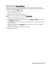
Selection of the appropriate sweep time depends on the device being measured; the longer the
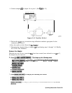
electrical delay of the device under test, the slower the sweep rate must be. A good way to tell
when the sweep rate is slow enough is to put the vector network analyzer into a list frequency
mode of sweeping, and compare the data. In this mode, the vector network analyzer does not
sweep the frequency, but steps to each listed frequency point, stops, makes a measurement,
then goes on to the next point. Because errors do not occur in the list frequency mode, it can
be used to check the data. The disadvantage of the list frequency mode is that it is slower than
sweeping.
648
Optimizing Measurement Results