


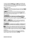
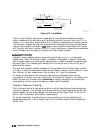

Actual
Directlvity
‘\
‘--Efiechve
Directlvity
After
CorrectIon
(DA-
D,
=
-I-,)
Tof
Load
(r,)
Measured
Directivity
Before
Correctlo”
CD,)
pb6112d
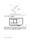
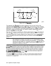
Figure 6-38. Measured Effective Directivity
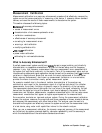
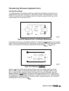
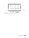
Next, a short circuit termination whose response is known to a very high degree is used to
establish another condition (see
F’igure
6-39).
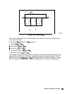
V
5
,lA=11180'
s
(-~)(ERF)
II,,,,
=
EDF+
____
~-EsF(-~)
J
pg656d
Figure 6-39. Short Circuit
Termination
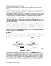
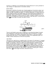
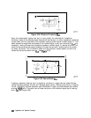
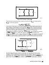
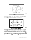
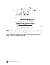
The open circuit gives the third independent condition. In order to accurately model the phase
variation with frequency due to fringing capacitance from the open connector, a specially
designed shielded open circuit is used for this step. (The open circuit capacitance is different
with each connector type.) Now the
values
for
Enr
, directivity,
Esr
, source match, and
ERF,
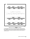
reflection frequency response, are computed and stored (see Figure 6-40).
6-64
Application and Operation Concepts