


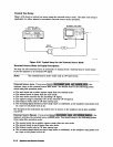
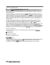
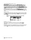
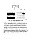

Coupling Power Between Channels 1 and 2
the fundamental on channel 1 and the harmonic on channel 2. D2/Dl to
D2
ratios the two,
showing the fundamental and the relative power of the measured harmonic in
dBc
You must
,.,.:
. . .
. . . . . . . . . .,.,.,,.
,.:
;
.;,s
..,.,..
%
. . . . . . . . . .
_
*
,.
,..
_
.
.
..:
(
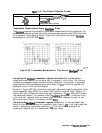
uncouple
channels
1
ad
2
for
this
measurement,
using the
:gfJwm
~~.~~.~~i~~~.
s&key
set
to
OFF
to allow alternating sweeps.
After uncoupling channels 1 and 2, you may want to change,the fundamental power and see
ii
the resultant change in relative harmonic power (in
dBc).
.~~~~~.~~~~~~~~~~~~~
allows you to
. .
i
. . . . . . .
s..w
cc:.:
i../
i
change the power of both channels simultaneously, even though they are uncoupled
in
all other
respects.
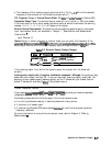
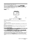
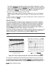
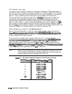
Frequency Range
The frequency range is determined by the upper frequency range of the instrument or system
(3 or 6
GHz)
and by the harmonic being displayed. The 6
GHz
operation requires an HP 87533
Option 006.
Table
6-9 shows the highest fundamental frequency for maximum frequency and
harmonic mode.
‘lhble
6-9. Maximum Fundamental Frequency using Harmonic Mode
HarmolliC
bhximum Fundamental
Frequency
I
Measnred
HP
876IE
HP
875i)E
Accuracy
and input power
Refer to Chapter 7,
“Specifications and Measurement Uncertainties.
n
The
maxims
recommended input power and maximum recommended source power are related
specifications.
Using power levels greater than the recommended values, you may cause undesired harmonics
in the source and receiver. The recommended power levels ensure that these harmonics are
less than 45
dBc
Use test port power to limit the input power to your test device.
6-124
Application and Operation Concepts