


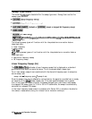
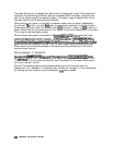
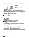
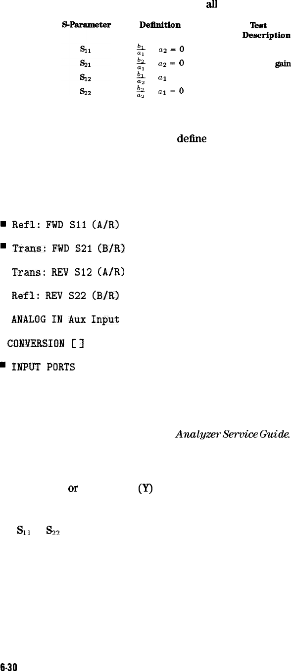
S-parameters are exactly equivalent to the more common description terms below, requiring
only that the measurements be taken with
a.ll
test device ports properly terminated.
Deilnition
LL
z
a2
=
0
a1
ap
-
0
!!A
a2
a1
= 0
h
a2
a1
=o
!bt
set
Description
Input reflection coefficient
Forward
@in
Reverse gain
Output reflection coefficient
Direction
FWD
FWD
REV
REV
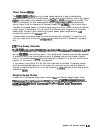
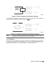
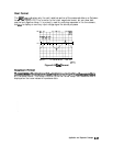
The S-Parameter Menu
The S-parameter menu allows you to
del?ne
the input ports and test set direction for
S-parameter measurements. The analyzer automatically switches the direction of the
measurement according to the selections you made in this menu. Therefore, the analyzer can
measure all four S-parameters with a single connection. The S-parameter being measured is
labeled at the top left comer of the display.
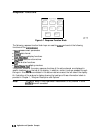
The S-parameter menu contains the following softkeys:
w
Refl:
FWD
Sll
(A/R)
.
Tram:
FWD
S21
(B/R)
n
Tram:
REV
S12
(A/R)
n
Refl:
REV
S22
(B/R)
n
ANALOG
IN
Aux
Input
.
CONVERSION
[
1
provides access to the conversion menu.
.
INPUT
PORTS
provides access to the input ports menu.
Analog In Menu
This menu allows you to monitor voltage and frequency nodes, using the analog bus and
internal counter. For more information, refer to Chapter 10, “Service Key Menus and Error
Messages” in the
HP 8753E Network
Analgzer
Service
Guide.
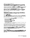
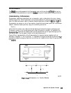
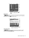
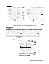
Conversion Menu
This menu converts the measured reflection or transmission data to the equivalent complex
impedance (Z)
or
admittance
(Y)
values. This is not the same as a two-port Y or Z parameter
conversion, as only the measured parameter is used in the equations. Two simple one-port
conversions are available, depending on the measurement configuration.
An
SI1
or
s2
trace measured as reflection can be converted to equivalent parallel impedance or
admittance using the model and equations shown in Figure 6-9.
6-30
Application and Operation Concepts