


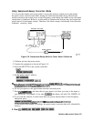
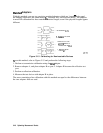

Perform the Z-port Error Corrections
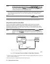
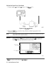
1. Connect adapter
A3
to adapter
A2
on port 2. (See
Figure
5-12.)
NETWORK
ANAL’IZER
REFERENCE
PORT
1
REFERENCE
pg647e
Figure 5-12.
‘lko-Port
Cal Set 1
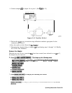
2. Perform the
2-port
error correction using calibration standards appropriate for the
connector type at port 1.
Note
When using adapter removal calibration, you must save calibration sets to the
internal disk, not to internal memory.
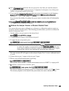
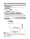
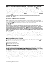
Caution
Do not mistake the
Iine
switch for the disk eject button. See the figure below.
If the
Iine
switch is mistakenly pushed, the instrument
wiII
be turned off,
losing
all
settings and data that have not been saved.
DISK EJECT
BUTTON
1
LINE
SWITCH/
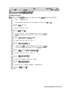
3.
Save
the results to disk. Name the
file
“PORTl.”
542
Optimizing Measurement Results