


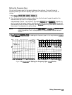
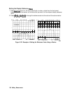
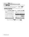

Measuring Magnitude and Insertion Phase Response
The analyzer allows you to make two different measurements simultaneously. You can make
these measurements in different formats for the same parameter. For example, you could
measure both the magnitude and phase of transmission. You could also measure two different
parameters
(Sll
and
S&.
This measurement example shows you how to measure the maximum amplitude of a SAW
filter
and then how to view the measurement data in the phase format, which provides information
about the phase response.
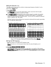
Measuring the Magnitude Response
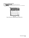
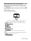
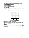
1. Connect your test device as shown in Figure 2-29.
NETWORK
ANALYZER
DEVICE
UNDER TEST
Figure 2-29. Device Connections for Measuring a Magnitude Response
2. Press
1presei)
and choose the measurement settings. For this example the measurement
parameters are set as follows:
You may also want to select settings for the number of data points, averaging, and IF
bandwidth.
3. Substitute a thru for the device and perform a response calibration for both channel 1 and
channel 2.
Press
Icall
..CALIBRATE MENU RESPONSE THRU...............................................................
......;:
.
..a..
.........
i..
.......................................
.:../._;;;;..~..~
...................
.
.........................
...................
.....
...........
.._
........................................................................................
.......................
...
press
(-1
f~&#$~
;?$#@R@.
...................................... . . . . . .
..........
.
::.
.....
,:,:
:‘“:
......
.
a:..::
...
i..
............
...................
...
.._......................... ...............................
Making Measurements
2.37