


Conversion Compression Using the Frequency Offset Mode
Conversion compression is a measure of the maximum RF input signal level, where the mixer
provides linear operation. The conversion loss is the ratio of the IF output level to the RF input
level. This value remains constant over a specified input power range. When the input power
level exceeds a certain maximum, the constant ratio between IF and RF power levels will begin
to change. The point at which the ratio has decreased 1
dR
is called the 1
dB
compression
point. See Figure 3-19.
Input Signal (RF)
Input Signal (RF)
pb6100d
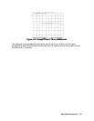
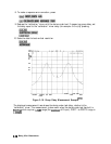
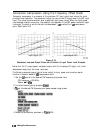
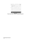
Figure 3-19.
Conversion Loss and Output Power as a Function of Input Power Level Example
Notice that the IF output power increases linearly with the increasing RF signal, until mixer
compression begins and the mixer saturates.
The following example uses a ratio of mixer output to input power and a marker search
function to locate a
mixer’s
1
dR
compression point.
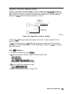
1. Set the
Lo
source to the desired CW frequency and power level.
CW frequency = 600 MHz
Power
=
13
dl3m
2. Initialize the analyzer by pressing
B.
3.
To
set the desired CW frequency and power sweep range, press:
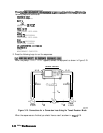
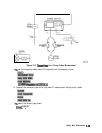
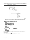
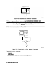
4. Make the connections, as shown in
Figure
3-20.
3-28 Making Mixer Measurements