


CHl
511
Re
5
mU/REF
G
U
1' -4.832 rnU
hp
56!
5
ns
COV
I I
I
I I I
I
I
I
CHI
ill
Re 5
mU/REF
0
"
1:
2.9207
mu
m
3
ll!i6
ns
Cur
MARKER 1
2.456
“5
4
?U, 41
mm
CHl
CTAPT
0
s
STOP 10
"5
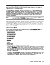
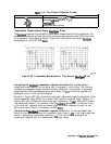
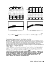
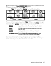
(a)
Crimped
Cable
(Capacitlvej
(b)
Frayed
Cable
(Inductive)
pg6123d
Figure 6-67. Low Pass Step Measurements of Common Cable Faults (Real Format)
Transmission Measurements In Time Domain Low Pass
Measuring small signal transient response using low pass step.
Use the low pass mode to
analyze the test device’s small signal transient response. The transmission response of a device
to a step input is often measured at lower frequencies, using a function generator (to provide
the step to the test device) and a sampling oscilloscope (to analyze the test device output
response). The low pass step mode extends the frequency range of this type of measurement to
3
GHz
(6
GHz
with an analyzer Option 006).
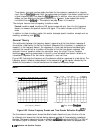
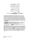
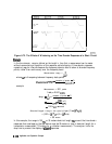
The step input shown in Figure 6-68 is the inverse Fourier transform of the frequency domain
response of a thru measured at calibration. The step rise time is proportional to the highest
frequency in the frequency domain sweep; the higher the frequency, the faster the rise time.
The frequency sweep in Figure 6-68 is from 10 MHz to 1
GHz.
Figure 6-68 also illustrates the time domain low pass response of an amplifier under test. The
average group delay over the measurement frequency range is the difference in time between
the step and the amplifier response. This time domain response simulates an oscilloscope
measurement of the amplifier’s small signal transient response. Note the ringing in the
amplifier response that indicates an under-damped design.
Application and Operation Concepts
6-133