


2.
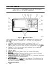
Stimulus Stop Value. This
value could be any one of the following:
n
The stop frequency of the source in frequency domain measurements.
n
The stop time in time domain measurements or CW sweeps.
a
The upper limit of a power sweep.
When the stimulus is in center/span mode,
the,
s?an is shown in this space. The stimulus
values can be blanked, as described under
~‘~~~~~‘~~~~~~~
Key” in Chapter 9, “Key
Definitions.
n
(For CW time and power sweep measurements, the CW frequency is displayed centered
between the start and stop times or power values)
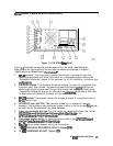
3. Status Notations.
This area shows the current status of various functions for the active
channel.
The following notations are used:
Avg
Cm
CA
Del
ext
Ofs
Of?
Gat
Sweep-to-sweep averaging is on. The averaging count is shown immediately
below. (See
“(Avg)
Key” in Chapter 9, “Key
Definitions.
“)
Error correction is on. (For error-correction procedures, refer to Chapter 5,
“Optimizing Measurement Results.” For error correction theory, refer to Chapter
6, “Application and Operation Concepts.
“)
Stimulus parameters have changed from the error-corrected state, or interpolated
error correction is on. (For error-correction procedures, refer to Chapter 5,
“Optimizing Measurement Results.” For error correction theory, refer to Chapter
6, “Application and Operation Concepts “)
Full two-port error-correction is active and either the power range for each port
is
different
(~coupled),
or
the
~~~~~5~~~~~:
is
a&vat&.
me
annotation
i
..:: :.:.::: .._..........
i;;;;u....zu;
i.......
.:..
.
.
.
.
..a
L.::..:
::..::.
.
.
.
.
.
.
.
.
.
occurs because the analyzer does not switch between the test ports every sweep
under these conditions. The measurement stays on the active port after an
initial cycling between the ports (The active port is determined by the selected
measurement parameter.) You can update all the parameters by pressing
LMenu)
~~~~~~~~
,
::..:.
i
.::..
../:...A;
. . .
. . . . .
..~.;..::..~.;..;;
. . .
.
.::.: ...,.
L
.
.
. . .
or
~
key.
Electrical delay has been added or subtracted, or port extensions are active. (See
Chapter 6, “Application and Operation
Concepts”and
“(~J
Key” in Chapter
9, “Key
Dehnitions.“)
Waiting for an external trigger.
Frequency offset mode is on. (See “Frequency Offset Operation” in Chapter 6,
“Application and Operation Concepts.
“)
Frequency offset mode error, the IF frequency is not withln 10 MHz of expected
frequency. LO inaccuracy is the most likely cause. (See “Frequency Offset
Operation” in Chapter 6, “Application and Operation Concepts.
“)
Gating is on (time domain Option 010 only). (For time domain measurement
procedures, refer to Chapter 2, “Making Measurements.” For time domain theory,
refer to Chapter 6 “Application and Operation Concepts.“)
1-8
HP
6753E
Description and Options