


However, there are two
coniigurations
that may not appear to function “properly”.
1.
2.
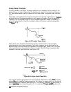
Channel 1 requires one attenuation value and channel 2 requires a different value. Since
one attenuator is used for both testports, this would cause the attenuator to continuously
switch power ranges.
With Option 007 (mechanical transfer switch), channel 1 is driving one test port and channel
2 is driving the other test port. This would cause the test port transfer switch to continually
cycle. The instrument will not allow the transfer switch or attenuator to continuously
switch ranges in order to update these measurements without the direct intervention of the
operator.
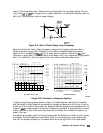
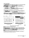
If one of the above conditions exists, the test set hold mode will engage, and the status
notation
tsH
will appear on the left side of the screen. The hold mode leaves the measurement
function in only one of the two measurement paths. lb update both measurement setups,
press
LMenu)
~~~~~~~~-;.
Refer
to
“Source
Attenuator
&&itch
Rote&ion”
earlier
h
m
.._.................
chapter for more information on this condition.
Four-Parameter Display Functions
The
(j-d
menu allows you to enable the auxiliary channels and
conhgure
a four-parameter
display. This section describes those functions in the
ljj)
menu which affect the
four-parameter display. See “Using the Four-Parameter Display Mode” in Chapter 2 for the
procedure to set up a four-parameter display.
A full two-port calibration must be active before an auxiliary channel can be enabled. A full
two-port calibration can be performed before enabling the auxiliary channels, or it may be
recalled from a previously saved instrument state. If a full two-port calibration is recalled from
an instrument state, you may have to change some of the parameters of the recalled state so
that you can test your device.
Once a full two-port calibration is active, you can enable the auxiliary channels by setting
. . . . . . . . . . . . . . . . . . . . . . . . . . . . . . . . . . . . . . . . . . . . . . . . . . . . . . . . . .
~.. :
:~
“,~~,,,~.~.~.~.~.~.~.~
,.
_
__i
.:.
.,.,.;
_
.,...
_
,.,..,.,.,.,.,.,.,.,.,.,.,.,.,.,.,.,.,....
;..
,,
~~~~~~~6~~
to
#.
For
example,
if
channel
1
is
a&&e,
pressing
~~~~~~~~~~~
,;~,.:.::.:.~~.~~:;;~~,.~,.~~~:.:.~.:.:.:.:.:.:.::.:.:.:
.,,.
:.:.::.:.:.:.:.:.,.:.:.:.:.:.:.:.:.:.:.:.:.:.:.:.r
,,..,;
./..............
__ . . . . . . . .
.;;;;..;;;;;;x . . . . . . . . . . . . . . . . . . . . . . .
~...~.~~..~.,..;.,/;;;..............................~ii
. . .
.
. . .
..A
.>:..a
. . . . . . . . :..:..a
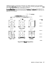
enables channel 3 and its trace appears on the display. Channel 4 is similarly enabled and
viewed when channel 2 is active:
-
An important point to remember about the auxiliary channels is that they always have the
same stimulus parameters as their primary channels See “Channel Stimulus Coupling” earlier
in this chapter.
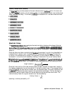
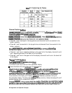
Customizing the Display
When one or both auxiliary channels are enabled (see “Using the Four-Parameter
Display
Mode”
in
chapter
2,
=Making
Measurements")
~~~~~,~,~~~~~~~
and
3
.:::.l:::.:::::.~.:...;:::
:.:
. .
.
.
.
:..::::.::::::::.:
::::::::::v~i::~.A::::::::.v::u:
_
,.
.
.
.,, ,,.,,,,,..,,.,,,,.
., ..-..
..i.~
.
.
.
.
.
.
.
.
.
.
.
.
.
.
.
.
;:;.
...~.CT~.~
.i.:::.
~~~~~~~~~~~~~~~~:~~~~
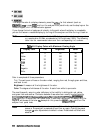
&era&
to
produce
different
&splay
con@rations
according
to
,:...:.:
I~..:.:.~~.~~~~~:.:.:.:.:~~~:
. . . . .
;.>:
. . . . .
:;::.:.:.:.:.::
_
p
.,.,.,.
:'....
~.~.;..A
_
_
. . . . . . . . . . .
_
..::..::..
;...:.;
%ble 6-2.
Application and Operation Concepts
645