


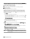


Frequency Response and Isolation Error-Corrections
n removes frequency response of the test setup
n
removes isolation in transmission measurements
w
removes directivity in reflection measurements
You can make a response and isolation correction for the following measurements:
w
reflection measurements
N
transmission measurements
n
combined reflection and transmission measurements
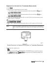
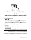
Response and Isolation Error-Correction for Reflection Measurements
Although you can perform a response and isolation correction for reflection measurements,
Hewlett-Packard recommends that you perform an
S1l
one-port error-correction; it is more
accurate and just as convenient.
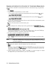
1. Press
B.
2. Select the type of measurement you want to make.
•I If you want to make a reflection measurement on PORT 1 (in the forward direction,
&I),
leave the instrument default setting.
q If you want to make a reflection measurement on PORT 2 (in the reverse direction,
S&,
press:
3. Set any other measurement parameters that you want for the device measurement: power,
sweep type, number of points, IF bandwidth.
4. To access the measurement correction menus, press:
Ical]
.,:
_.,.
.,...;:.:...,...:.:.:.:.:.:.:.:........
,,
,.I
__/,
.,..,..,.,.
_
6.
If your calibration kit is different than the kit specified under the
~~~~~~~~~~~~~;~
softkey,
i..ii
..-.-....
press:
. . . . . .
i
. . . . . .
. . . ..T
. . . . . . . . . . . .. . . . . . . . .
:
_
y:
.,
~~~~~~,~~~,~
~~~~~~~~~~~~
(select
you
type
of
kit)
;~~
,,,
,,,
,,
,,,
,,,..,.
*
_
_
/
.._......
.._
..-....
If your type of calibration kit is not listed in the displayed menu, refer to the “Modifying
Calibration Kit Standards” procedure, located later in this chapter.
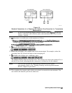
6.
To
select a response and isolation correction, press:
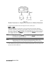
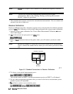
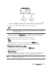
7. Connect the short or open calibration standard to the port you selected for the test port
(PORT 1 for
S11
or PORT 2 for
$2).
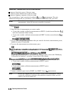
Note
Include any adapters that you will have in the device measurement. That is,
connect the standard device to the particular connector where you will connect
your device under test.
5-14
Optimizing Measurement Results